Performance Verification
4.7 External Trigger Level Test
4
4.7 External Trigger Level Test
Proceed as follows:
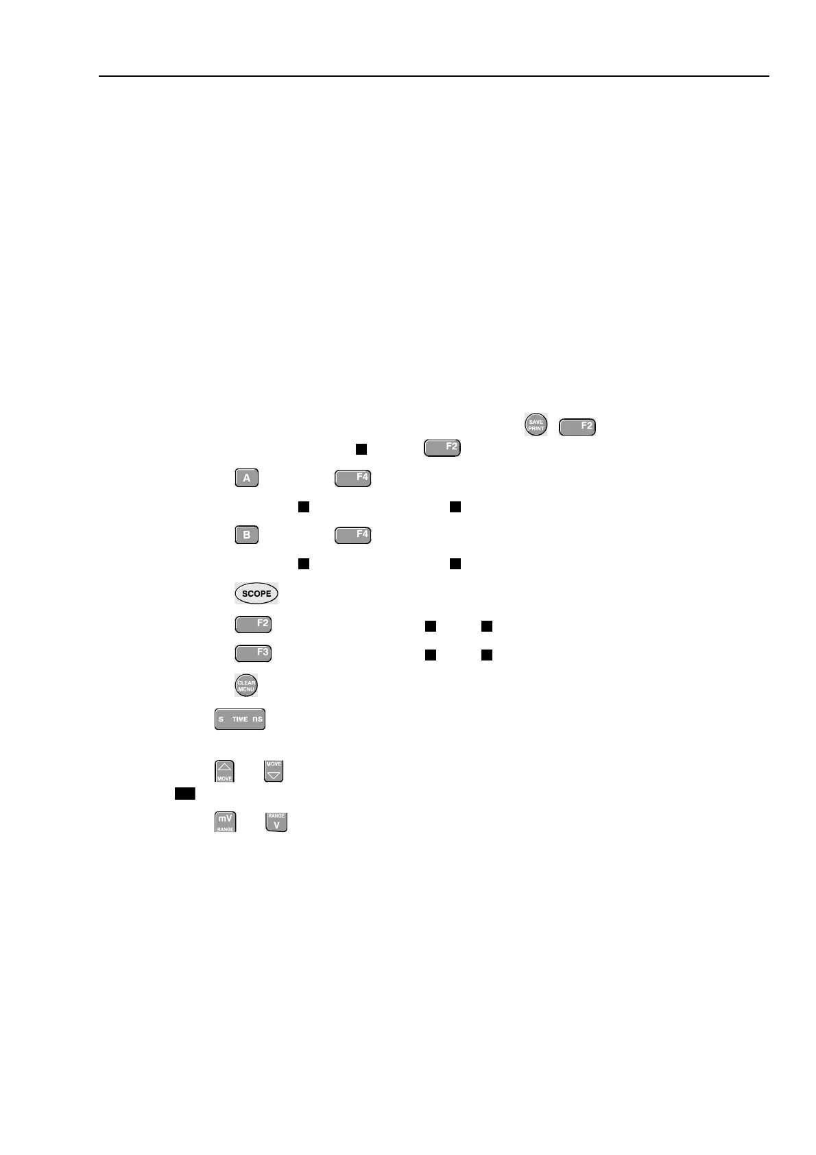
1. Connect the test tool to the 5500A as shown in Figure 4-18.
al55ex2w.bmp
Figure 4-18. Test Tool Meter/Ext Input to 5500A Normal Output
2. Select the following test tool setup:
• Reset the test tool
• Press
• Using
select the
TRIGGER OPTIONS...
menu
⇒ Select
On Edges...
from the
TRIGGER OPTIONS
menu
⇒ Select
Update: Single Shot | Noise reject Filter: On
• Using
EDGE TRIG
select
Ext
.
• Using
SLOPE
select positive slope triggering (trigger icon ).
• Using
Ext LEVEL
select
1.2 V
3. Set the 5500A to source 0.4V dc.
4. Verify that no trace is shown on the test tool display, and that the status line at the
display top shows
SINGLE MANUAL or SINGLE WAITING
. If the display shows the
trace, and status
SINGLE HOLD
then press to re-arm the test tool for a trigger.
5. Set the 5500A to source 1.7 V
6. Verify that the test tool is triggered by checking that the trace becomes visible.
To repeat the test, start at step 3.
7. Set the 5500A to Standby.