Fluke 19xB-19xC-2x5C
Service Manual
6-6
Referring to Figure 6-5, use the following procedure to remove the main PCA unit.
1. Open the test tool (see Section 6.2.4).
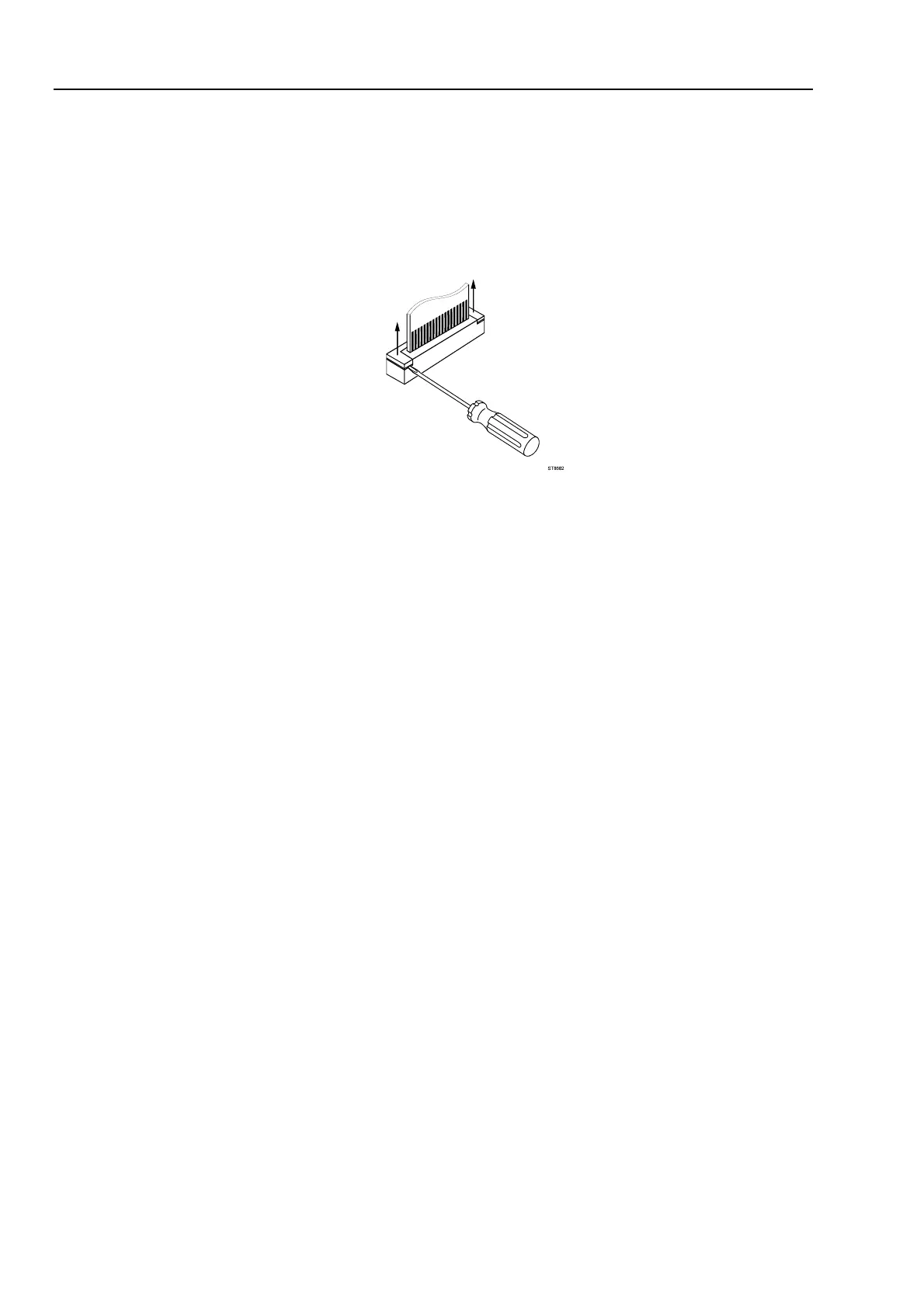
2. Disconnect the blue keypad foil (item 5) flat cable, and the white LCD (item 7) flex
cable. Unlock each cable by lifting the connector latch at the left and right edge
using a small screw-driver, see Figure 6-6. The latch remains attached to the
connector body.
ST8682.WMF
Figure 6-6. Flex Cable Connectors
3. Unplug the two-wire backlight cable.
Warning
If the battery pack or the power adapter is connected, the LCD
backlight voltage on the wire cable is 400V ! (when the test tool
is on).
4. Remove the two screws (item 14) that secure the Main PCA unit to the top case.
5. Slide the Main PCA unit in the input cover direction to remove it.
6. To remove the fan from the main PCA unit, unplug the fan connector and unscrew
the screws item 24.
6.2.6 Removing the Display Assembly
There are no serviceable parts in the display assembly. Referring to Figure 6-5, use the
following procedure to remove the display assembly.
1. Remove the main PCA unit (see Section 6.2.5).
2. Unscrew the four screws item 10.
3. Remove the display assembly (item 7) with the mounting frame (item 8).
To prevent finger contamination, wear cotton gloves, or handle the display assembly
by its edges.
4. Remove the display from the mounting frame.
 Loading...