Calibration Adjustment
5.3 Starting the Calibration
5
To enter the calibration mode proceed as follows:
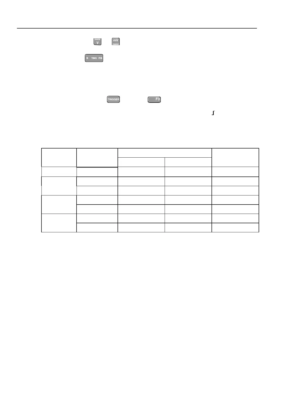
• Press and hold
, press and release , release
The display shows the
CAL MODE
(Calibration Adjustment) screen.
The display shows the calibration step
Warming Up (CL 0200)
, the calibration status
:IDLE (valid)
or
:IDLE (invalid)
, and the softkey menu.
Continue as indicated in section 5.2.
You can leave the calibration mode without changing the calibration data by turning the
test tool off.
Explanation of screen messages and key functions.
When the test tool is in the calibration Mode, only the
to soft keys, the
key, and the key can be operated, unless otherwise stated.
The calibration adjustment screen shows the actual calibration step (name and number)
and its status:
Cal Name (CL nnnn) :Status (...)
Cal Name
Name of the selected calibration step, e.g.
WarmingUp
(CL nnnn)
Number of the calibration step
Status (...)
can be:
IDLE (valid)
After (re)entering this step, the calibration process is not started.
The calibration data of this step are valid. This means that the
last time this step was done, the calibration was successful. It
does not necessarily mean that the unit meets the specifications
related to this step!
IDLE (invalid)
After (re)entering this step, the calibration process is not started.
The calibration data are invalid. This means that the last time this
step was done, the calibration was not successful. Most probably
the unit will not meet the specifications if the actual calibration
data are saved.
BUSY aaa% bbb%
Calibration adjustment step in progress; progress % for Input A
and Input B. During WarmingUp the elapsed time is shown.
READY
Calibration adjustment step finished.
Error :xxxx
Calibration adjustment failed, due to wrong input signal(s) or
because the test tool is defective.
If the error code is <5000 you can repeat the failed step.
If the error code is ≥5000 you must repeat the complete final
calibration (start at 5.6.1).
Functions of the keys F1-F4 are:
PREV
select the previous step
NEXT
select the next step
CAL
start the calibration adjustment of the actual step
EXIT
leave the calibration mode