Performance Verification
4.6 Scope Input A&B Tests
4
Table 4-10. Input B Trigger Sensitivity Test Points
UUT UUT 5500A SC... MODE levsin UUT
Model Time base Initial Input Voltage Frequency Trigger Amplitude
ALL 200 ns/div 100 mV pp 5 MHz 0.5 div
192B-C 10 ns/div 400 mV pp 60 MHz 1 div
10 ns/div 800 mV pp 100 MHz 2 div
196B-C, 215C 10 ns/div 400 mV pp 100 MHz 1 div
10 ns/div 800 mV pp 150 MHz 2 div
199B-C, 225C 10 ns/div 400 mV pp 200 MHz 1 div
10 ns/div 800 mV pp 250 MHz 2 div
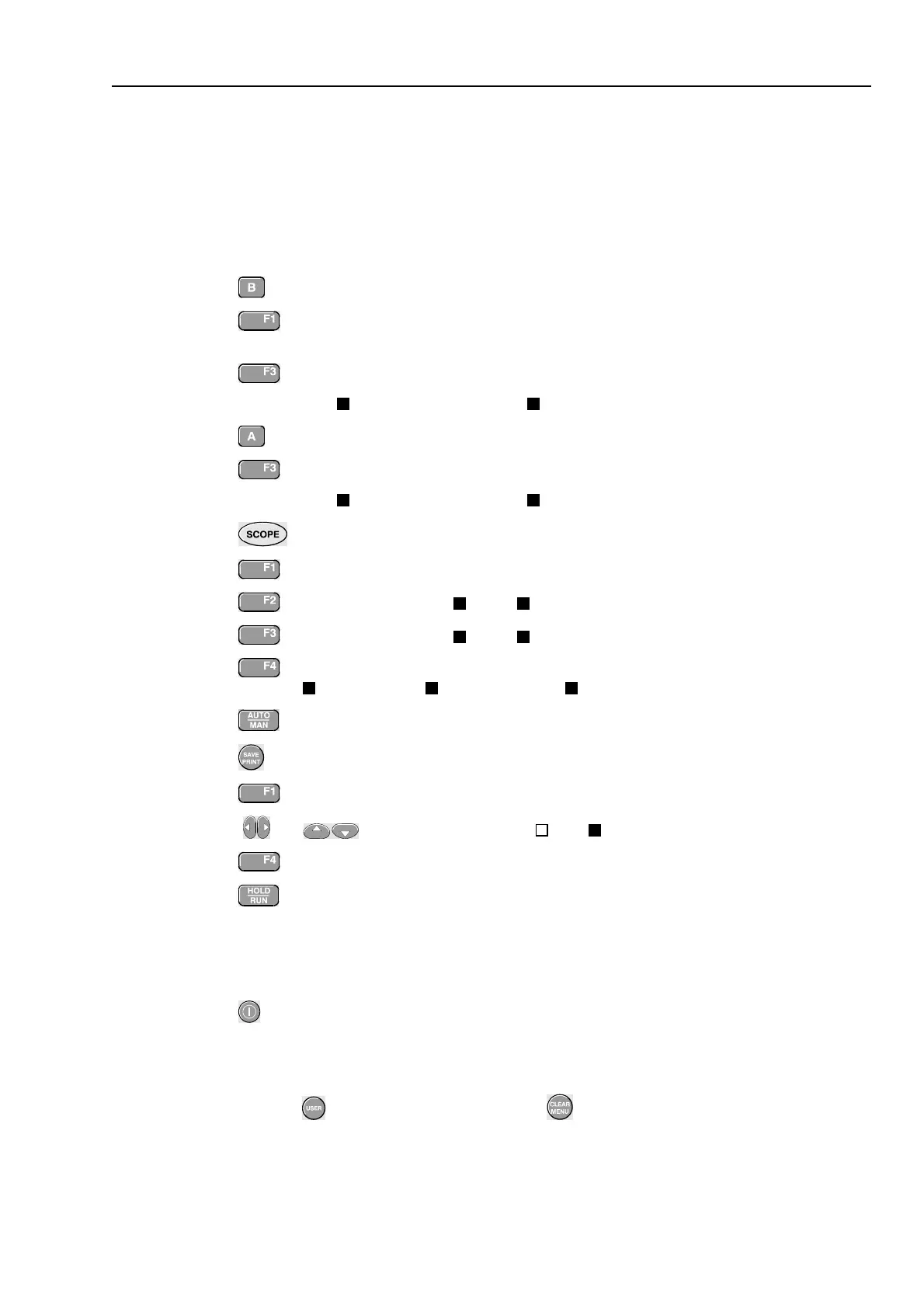
4.6.12 Input B AC Voltage Accuracy (HF) & Bandwidth Test
Proceed as follows to test the Input B high frequency automatic scope ac voltage
measurement accuracy, and the bandwidth:
1. Connect the test tool to the 5500A as for the previous test (see Figure 4-7).
2. Select the following test tool setup:
• Recall the created SETUP 1 (see section 4.4.3): press
,
RECALL
,
select
SCREEN+SETUP 1
, press
RECALL SETUP
.
• Press , then press
READING 2
, and select
on B | V ac
.
• Press to select autoranging (
AUTO
in upper right LCD edge)
• Using and change the sensitivity range to select manual sensitivity
ranging, and lock the Input B sensitivity range on 500 mV/div.
3. Set the 5500A to source a sine wave, to the first test point in Table 4-11.
4. Observe the Input B reading and check to see if it is within the range shown under
the appropriate column of table 4-11.
5. Continue through the test points.
6. When you are finished, set the 5500A to Standby.
Table 4-11. HF AC Voltage Verification Points
UUT 5500A SC... MODE levsin UUT
Model Voltage Frequency Reading B
all 2.545 Vpp 1 MHz 835 mV to 965 mV
all 2.545 Vpp 25 MHz 790 mV to 1.010 V
192B-C 2.545 Vpp 60 MHz >630 mV
196B-C, 215C 2.545 Vpp 100 MHz >630 mV
199B-C, 225C 2.545 Vpp 200 MHz >630 mV