Disassembling the Test Tool
6.1. Introduction 6
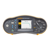
6-3
6.1. Introduction
This section provides the required disassembling procedures. The printed circuit
assembly removed from the test tool must be adequately protected against damage.
Warning
To avoid electric shock, disconnect test leads, probes and
power supply from any live source and from the test tool itself.
Always remove the battery pack before completely
disassembling the test tool. Only qualified personnel using
customary precautions against electric shock should work on a
disassembled unit with power on
6.2. Disassembly & Reassembly Procedures
6.2.1 Required Tools
To access all the assemblies, you need the following:
• Static-free work surface, and anti-static wrist wrap.
• #10 Torx screwdriver.
• Cotton gloves (to avoid contaminating the lens, and the PCA).
6.2.2 Removing the Tilt Stand & Hang Strap
Use the following procedure to remove the tilt stand and hang strap (Figure 6-5, item 15
and item 10).
1. Set the tilt stand to a 45-degree position respective to the test tool bottom.
2. The hinge consists of a circular raised rim in the tilt stand that is located over a
circular lowering in the bottom case. Pull sideward on the front edge of the tilt stand
until the hinge releases. Then rotate the stand to the rear to remove it. You can
remove the hangstrap now.
6.2.3 Replacing the Side-Strap, Changing the Side-Strap Position
The side-strap (figure 6-5, item 15) can be attached at the right or left side of the test tool.
Use the following procedure to replace the strap, or to change the strap position.
1. To remove the strap, unfold the strap ends (provided with Velcro tape), and pull the
ends out of the strap holders (item 16).
2. To change the strap position open the test tool (see Section 6.2.4), remove the strap
with the strap holders, attach them to the other side, and reassemble the test tool.
6.2.4 Opening the Test Tool, Removing the Battery
Use the following procedure to open the test tool, and to remove the battery:
1. Loosen the two M3 Torx screws that secure the input cover (Figure 6-1).
2. Loosen the two M3 Torx screws that secure the bottom holster (Figure 6-2).
3. Pull off the input cover and the bottom holster (Figure 6-3).
 Loading...