13
Installation and Operation Manual
SystemsSystems
2001 and 2002
Injector Above
Horizontal Plane
DO
DON'T
Injector Below
Horizontal Plane
INJECTOR ABOVE
HORIZONTAL PLANE
DO
INJECTOR BELOW
HORIZONTAL PLANE
FOAMPRO PADDLEWHEEL
FLOWMETERS
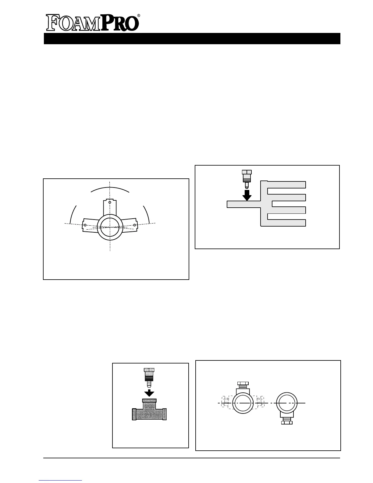
The FoamPro paddlewheel style flowmeter
fittings are specially designed tees that make
inspection and maintenance of the flow sensor
easy. The threads of the tees are NPT. In
horizontal runs the tees should be mounted as
close to upright as possible within the range
shown in Figure 8.
With the use of a MultiFlo interface, two to four
flowmeters may be monitored simultaneously.
A single injection point that will supply foam
agent to all foam discharge outlets is required.
F. INJECTOR FITTING
The brass injector fitting ensures foam
concentrate is injected into the center of the
water flow for better mixing. It is designed to fit
into a 1 inch NPT threaded connection on a pipe
tee that is installed in the discharge piping of the
fire pump (See Figure 9). The inlet of the fitting
is
1
/2 inch NPT female thread and the outer
threads are 1 inch NPT. The injector may also
be inserted into a weld
fitting with 1 inch NPT
female threads. It
MUST be mounted in
a place that is
common to all
discharges which
require foam
capability. This fitting
is not used if using a
FoamPro Main Waterway Check Valve. A
separate injection point is not possible for each
discharge. If multiple flowmeters are used, the
injector must be installed before the flow meters
at the inlet to their common manifold (See
Figure 10).
Most foam concentrates by nature mix with
water very quickly, so each discharge from a
manifold will receive equal concentrations if the
manifold is properly designed and installed.
G. CHECK VALVES
A
1
/2 inch NPT check valve meets NFPA
requirements for a non-return device in the
foam injection system. To prevent foam
concentrate flow from the foam concentrate tank
due to static head pressure, the foam
concentrate check valve shall have a 4 to 6 psi
[0.1 to 0.3 BAR] cracking pressure and shall be
capable of withstanding the pressures that will
be generated in the foam injection line. It is
always a good idea to inject foam at a horizontal
or higher angle to allow water to drain away
Figure 9. Injector
Fitting Installation
Figure 10. Injector Fitting Placement for
Multiple Discharges
Figure 11. Foam Injector Position
DON’T
Figure 8. Flowmeter Position Range
TEE SHOWN WITHOUT
SENSOR INSTALLED
85°
Max.
85°
Max.
Injector
Fitting