SOLO PLUS REFRIGERATION SYSTEM
CONTENTS PAGE INTRODUCTION
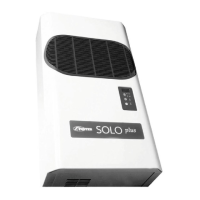
Introduction 23 Solo Plus is a range of packaged refrigeration
systems comprising of 10 Wall Models and 8
Technical Data 24 Ceiling Models.
The systems are pre-charged with refrigerant and
Access 25 pre-wired ready for installation into a coldroom with
only electrical connections to be made. No external
Controller Operation 25-26 drain is required.
Units will operate up to 43°C ambient conditions
Controller Parameters 27-33 (ISO Climate Class 5). If installed outside neither
the coldroom or the Solo is weatherproof, therefore
Controller Inputs / Outputs 34 suitable protection must be provided.
Probe Resistance Values 34
Electrical Connections 35
Fuses 36 Table 1. Storage Conditions °C
Unit Type Refrigerator Meat Freezer
Controller Fault Finding 37
Temp +10 +1/+4 0/-2 -18/21 -25
Model SP1HW SP1HW SP1HW SP1LW
Controller Emergency Repair 38 SP2HW SP2HW SP2HW SP2LW SP2LW
SP3HW SP3HW SP3HW SP3LW SP3LW
Routine Maintenance 38 SP4HW SP4HW SP4HW SP4LW SP4LW
SP5HW SP5HW SP5HW SP5LW SP5LW
Wiring Diagrams 39-44
SP1HC SP1HC SP1HC
SP2HC SP2HC SP2HC SP2LC SP2LC
SP3HC SP3HC SP3HC SP3LC SP3LC
SP4HC SP4HC SP4HC SP4LC SP4LC
SP5HC SP5HC SP5HC
NOTE!
Nomenclature “W” refers to Wall Model and “C” to
Ceiling model.
As each model operates at different temperatures it
will be necessary to set required operating
Temperature. See Operating and Installation Manual.
29