31
ACCESS TO THE UNIT COMPARTMENT / EVAPORATOR HOUSING
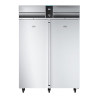
WALL MODEL
Front Panel: Remove the 2 fixing screws located under the base of the front panel and “pull forward”
releasing
it from the 4 “spring clips” located in each corner.
Condenser Fan After removing the front panel “pull upwards” the fan housing assembly releasing it from the 4
Assembly: “spring clips” located in each corner.
Evaporator Remove the 4 fixing screws from holding the drain pan in position and the side panel fixing
screws.
Assembly: Take the panel allowing access into the evaporator fan assembly.
CEILING MODEL
Unit Housing: Remove the 4 fixing screws from the front panel and “pull upwards” to release it from the 2
spring
clips located at the top.
Evaporator Remove the 4 fixing screws from the fan plate and lower allowing access to the evaporator fan
Assembly: motor and the evaporator assembly.
CONTROLLER OPERATION
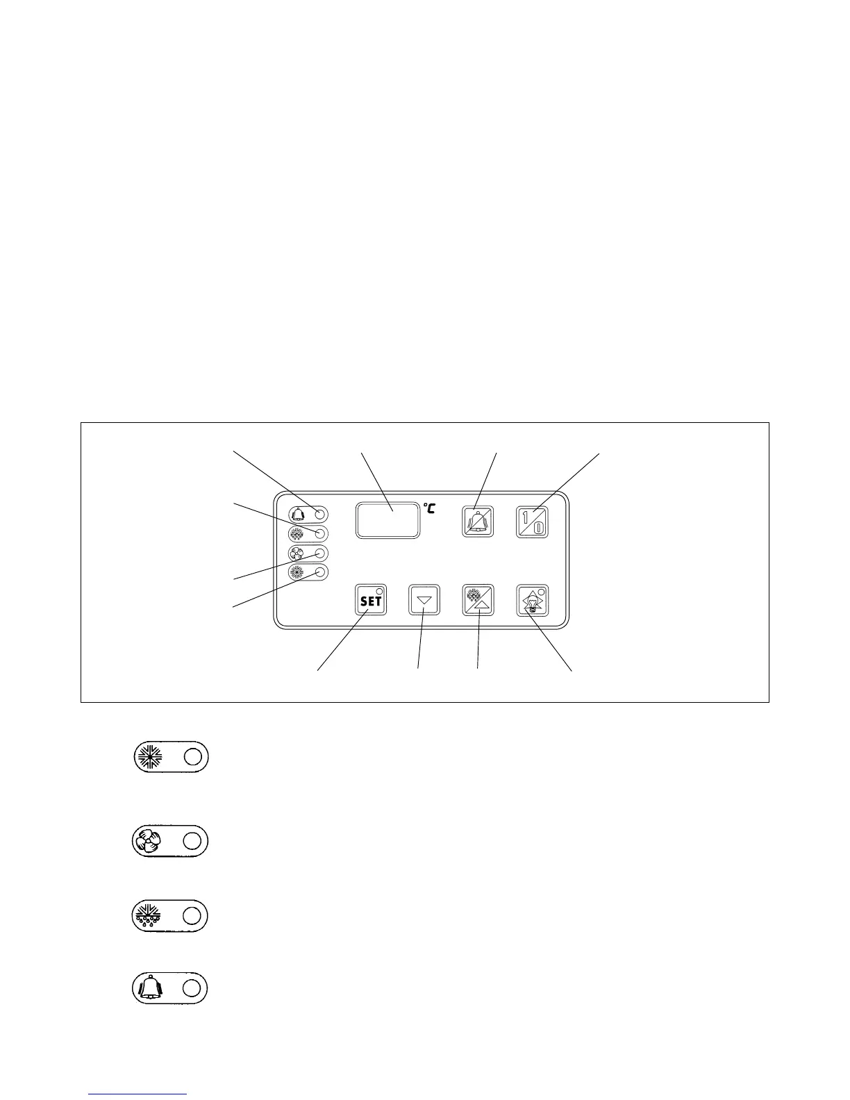
DESCRIPTION OF ELECTRONIC PANEL
1) COMPRESSOR LED (Green)
LIT: the compressor is running. The unit is cooling.
FLASHING: the compressor is in a delayed start mode
OFF: the compressor is OFF. The required room temperature has been reached.
2) EVAPORATOR FAN LED (Green)
LIT:
evaporator fan is running.
FLASHING: the evaporator fan is in a delayed start mode
OFF: the evaporator fan is OFF. Unit in defrost mode.
3) DEFROST LED (Yellow)
LIT:
automatic or manual defrost in progress.
4) ALARM LED (Red)
LIT: alarm mode: malfunctioning of a sensor, or intervention of pressure-stat or
room temperature outside preset limits.
OFF: unit working normally.
4 5 9 10
3
2
1
6 7 8 11