Foundry Hardware Installation Guide for the FES, FESX, and FWSX
3 - 12 © 2008 Foundry Networks, Inc. December 2008
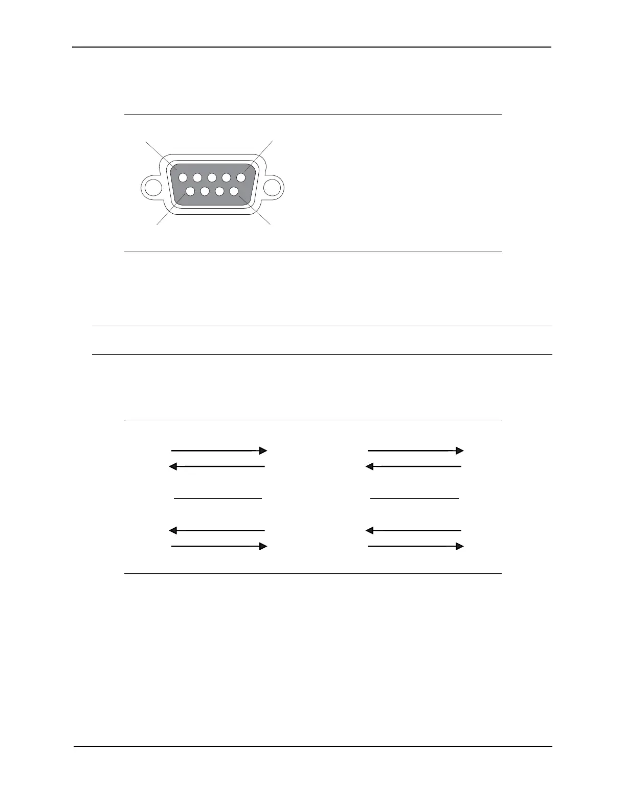
Figure 3.4 Serial port pin and signalling details
Most PC serial ports also require a cable with a female DB-9 connector.
Terminal connections will vary, requiring either a DB-9 or DB-25 connector, male or female.
Serial cable options between a Foundry switch or router and a PC or terminal are shown in Figure 3.5.
NOTE: As indicated in Figure 3.4 and Figure 3.5, some of the wires should not be connected. If you do connect
the wires that are labeled “Reserved”, you might get unexpected results with some terminals.
Figure 3.5 Serial port pin assignments showing cable connection options to a terminal or PC
1
5
96
Pin Assignment
DB-9 male
Pin Number
1
2
3
4
5
6
7
8
9
Switch Signal
Reserved
TXD (output)
RXD (input)
GND
CTS (input)
RTS (output)
Reserved
Reserved
Reserved
1
2
3
4
5
6
7
8
9
1
2
3
4
5
6
7
8
9
Reserved
DB-9 to DB-9
Female Switch
Reserved
Reserved
Reserved
Terminal or PC
1
2
3
4
5
6
7
8
9
8
3
2
20
7
6
4
5
22
Reserved
DB-9 to DB-25
Female Switch
Reserved
Reserved
Reserved
Terminal or PC