Foundry Hardware Installation Guide for the FES, FESX, and FWSX
6 - 4 © 2008 Foundry Networks, Inc. December 2008
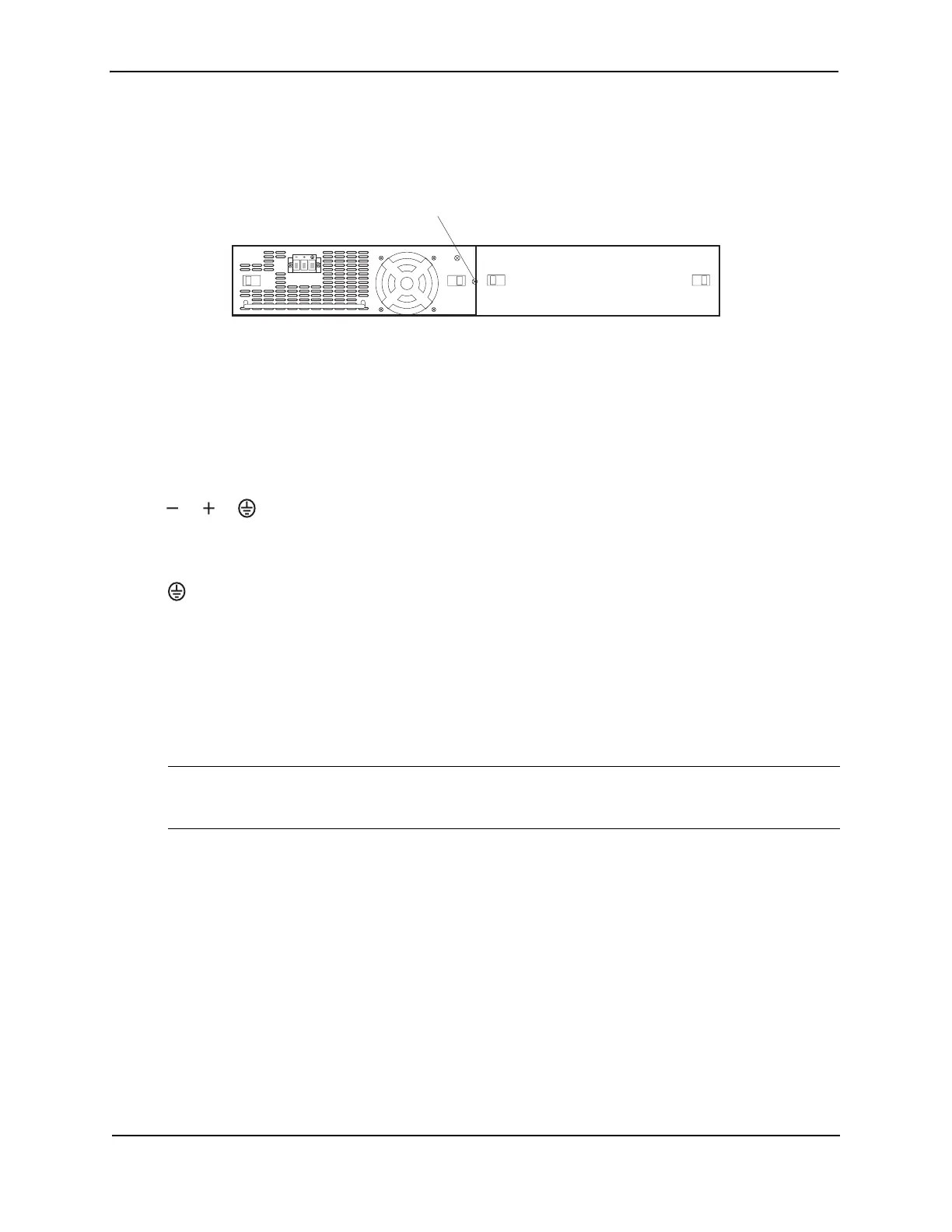
Installing a DC Power Supply
1. If necessary, before installing a power supply, remove the power supply locking screw located in the center
rear of the device (illustrated below).
2. If the empty power supply bay has a cover plate, press inward on the two latches near the edges of the cover
plate to unlock the plate, then remove the plate.
3. Remove the power supply from its packaging.
4. Prepare the positive, negative, and ground wires by stripping about 1/4" of insulation off the end of each one.
(Use 14 AWG wire.)
5. Loosen the three screws used to hold the wires in the connector. These are the wires under the following
markings
6. Slip the ground wire into the opening under the marking shown below until the wire is fully in place, then
tighten the screw to hold the wire in place.
7. Repeat for the negative (—) and positive (
+) wires.
8. Pull gently on each wire to make sure they are securely fastened in the connector.
9. With one hand, hold the bar on the front panel of the power supply. With the other hand, support the
underside of the power supply, and insert the power supply into the empty power supply slot. Press until the
supply is completely in the slot, so that the connectors on the back of the supply are fully engaged with the
pins on the power backplane.
CAUTION: Make sure you insert the power supply right-side up. It is possible to insert the supply upside
down, although the supply will not engage with the power backplane when upside down. The power supply is
right-side up when the power connector is on the left and the fan vent is on the right.
10. Press the two latches near the edges of the supply outward to lock the supply in place.
11. If necessary, replace the power supply locking screw.
12. After the power supply is properly inserted, connect the power source to the wires to activate the circuit.
Verifying Proper Operation
To verify the proper operation of the power supply after power on, you can observe the LEDs on the power supply.
After the FastIron device powers on, you can observe the LEDs on the front of the device to verify that it initialized
successfully. Table 6.1 outlines the LEDs, the desired state of each LED, possible abnormal states of each LED,
and what to do if an LED indicates an abnormal state.
Power Supply locking screw