Do you have a question about the FPG Fusion and is the answer not in the manual?
Welcome to FPG and its products, designed for optimal performance and visual merchandising appeal.
Read the instruction book carefully and follow recommendations for optimal operation and care.
Future Products Group Limited warrants the product for ONE YEAR against defects in workmanship or material.
Warranty liability does not cover loss or damage arising from misuse, neglect, alteration, or incorrect installation.
Exclusions include glass breakage, maladjustment by unqualified persons, routine cleaning, and fair wear and tear.
Liability depends on FPG assessment. Service is not guaranteed within a specific time limit.
No warranty claim accepted unless authorised by FPG prior to commencement of service.
Describes the Fusion Series cabinets, their independent heated/refrigerated sections, and power supply.
The refrigeration equipment is located in the base of the cabinet with openings for adequate ventilation.
Heat provided by radiant elements and a directly heated lower shelf, controlled from the back.
Each section has independent mains power supply. Heated section has a switch for heating/lighting.
No operator control switches on refrigerated section. Controller gear is in the base with displays and buttons.
Ensure that power is connected correctly to both cabinet sections.
The refrigeration system automatically defrosts periodically, optimised for minimal product temperature effect.
Maximum loading of any shelf must not exceed 15kg of evenly distributed products.
Switch off heated section after hours. Turn off refrigerated section lighting to conserve power.
Best to clean at end of day for optimal recovery before customers arrive.
Do not store explosive substances, such as aerosol cans with flammable propellant, in this appliance.
Requires specialist procedures for safe removal of refrigerant gasses and flammable foam materials.
Check mains switch, circuit breakers, or fuses. Remedy involves checking power and replacing components.
Possible causes include failed element, incorrect thermostat, or draughts. Remedies involve adjustment or replacement.
Check power supply, condenser temperature, and airflow. Remedies include cleaning and checking components.
Check ambient temperature, coil icing, or thermostat faults. Remedies include de-icing, cleaning, and replacement.
Alarm indicates probe fault. Check wiring and probe resistance, then repair or replace as required.
HA: High cabinet temp; HA2: High discharge pipe temp. Check cooling system and refrigerant.
ALWAYS TURN POWER SUPPLY OFF BEFORE CLEANING. UNIT IS NOT WATERPROOF.
Clean painted, stainless steel, or aluminium surfaces with hot soapy water or metal cleaning compound.
Condensate tray: do not fill or hose. Shelves/Trays: removable, clean with soapy water or dishwasher.
Lift fan deck/cover carefully, avoid damaging fan leads or coil fins. Ensure correct re-assembly.
Use wet/dry vacuum for debris. Do not hose. Fins are sharp; take extra care.
Ensure drain is free of debris. Blocked drains can cause ice build-up and damage coils.
To maintain performance, schedule cleaning regularly, initially monthly, adjusted to environmental conditions.
Keep condenser radiator clean for efficient performance. Regular vacuuming and periodic professional cleaning recommended.
Failure to carry out routine cleaning/servicing schedules will void the warranty on refrigeration equipment.
Installation must comply with local electrical, health & safety, and hygiene requirements.
Appliance not for use by persons with reduced capabilities unless supervised. Children must be supervised.
Unpack and check unit for damage. Report any damage to the carrier and supplier.
WARNING: APPLIANCE MUST BE EARTHED/GROUNDED. Equipotential bonding terminal provided.
Locate cabinet 20mm from wall. Do not block ventilation grill. Max ambient temp 32°C.
Cabinet must stand level for condensate drainage. Adjust jacking screws or use shims if needed.
Mains leads must only be replaced by manufacturer, service agent, or qualified person.
Circuits protected by circuit breaker. Check if lights do not work. Do not service without isolating power.
Light from LED strips. Individual modules not replaceable; use complete light unit. Select correct type.
Radiant elements above shelves, lower shelf directly heated. Probes above upper shelf for thermostat/thermometer.
Replace upper radiant elements by removing guard. Shelf elements require shelf assembly removal.
Controlled by thermostat on back. Turn clockwise to increase temperature. Check temperature gauge.
Located under removable panel on back. Houses MCB and LED power supply for heating/lighting circuits.
Circulates air to prevent surfaces becoming too hot. Ensure fan operates correctly and grill is clean.
DO NOT attempt to service refrigeration equipment without isolating the cabinet by unplugging from the mains socket.
Control gear chassis accessed by removing louver panel. Houses controller, isolation switch, MCB, and power supply.
Condenser unit and boil off element reached from front/rear. Remove screws to open back panel and louvers.
Keep condenser radiator and louvers clean for performance. Regular vacuuming and compressed air cleaning recommended.
Controller must NOT be tampered with by unqualified person. Indicates temp lower than cabinet air temp.
Probes for temp control, defrost termination, and overheating are located within the system.
Located in return air duct, indicates air temperature returning from display area before cooling coil.
Fan deck with two fans, electrically connected. Assembly is removable for servicing. Avoid trapping cables.
System includes water tray, level detector, and boil-off element. Element may be replaced by springing from bracket.
Check probe cleanliness and controller sensitivity. Test element by disconnecting probe wire.
Microprocessor controller with NTC/PTC probe inputs for temperature control, defrost, and alarms.
Regulation based on thermostat probe temperature and differential. Compressor cycles based on set point.
Controls defrost cycles (IdF, MdF) and modes (timed/probe). Defrost terminates when probe reaches pre-determined temperature.
Table lists functions for SET, DEF, UP, DOWN, +/- keys for operating the controller interface.
Table lists LED indicators and their modes (ON/Flashing) for compressor, defrost, alarms, and cycles.
Display min/max temperatures, reset memory. Press SET key for >3s to reset.
Display set-point by pressing SET. Change by pressing SET >2s and using UP/DOWN keys.
To start a manual defrost, press and hold the DEF key for more than 2 seconds.
Enter Programming mode by pressing SET+ keys for 3s. Use keys to select/change parameters.
Enter Hidden Menu by entering Programming mode, then pressing SET+ keys again for >7s.
Parameters can be moved between Hidden Menu and First Level by pressing SET+ keys.
Lock keyboard by pressing keys for >3s (POF message). Unlock by pressing keys for >3s (Pon message).
Specifies Dixell factory default settings. Refer to Specification section for FPG specific settings.
Table lists parameters, descriptions, ranges, and default settings for the Dixell controller.
Continues the table of Dixell controller parameters, descriptions, ranges, and default settings.
Program controller from Hot Key: turn OFF, insert key, turn ON. Download occurs automatically.
Table lists alarm messages (P1-P4, HA, etc.), their causes, and system outputs.
Procedures for alarm recovery for probe, temperature, and external alarms.
Table lists other messages like Pon, PoF, noP, noA with their respective causes.
Diagram shows connections for digital input, probes, supply, hot key/IV probe, and outputs.
Table details cabinet dimensions, weight, shelves, display area, refrigerant, and condensate capacity.
Table details voltage, power, current, connection type, lighting, and energy consumption.
Details operating temperature, internal humidity, and climatic class test conditions for the refrigerated section.
Specifies the settings for the Dixell XR40CX Controller that are specific to this FPG cabinet.
Table lists parameters, descriptions, and settings for the XR40CX controller specific to the FPG cabinet.
Cabinet designed to comply with relevant safety specifications like IEC 60335 series.
The cabinet does not contain Asbestos, PCBs, or Mercury in its construction.
FPG reserves the right to change specifications and construction as part of ongoing product improvement.
Table lists various spare parts with their corresponding FPG Part Numbers. Quote Serial Number when ordering.
Top view showing cabinet dimensions: width, depth, and height.
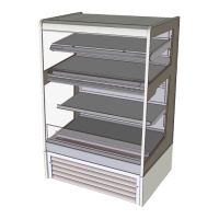
3D view of the cabinet, illustrating its overall appearance and structure.
Front view showing overall height, shelf details, and base grill.
Side view showing cabinet depth and internal shelf arrangement.
Rear view showing ventilation grills and access points.
| Brand | FPG |
|---|---|
| Model | Fusion |
| Category | Display Case |
| Language | English |