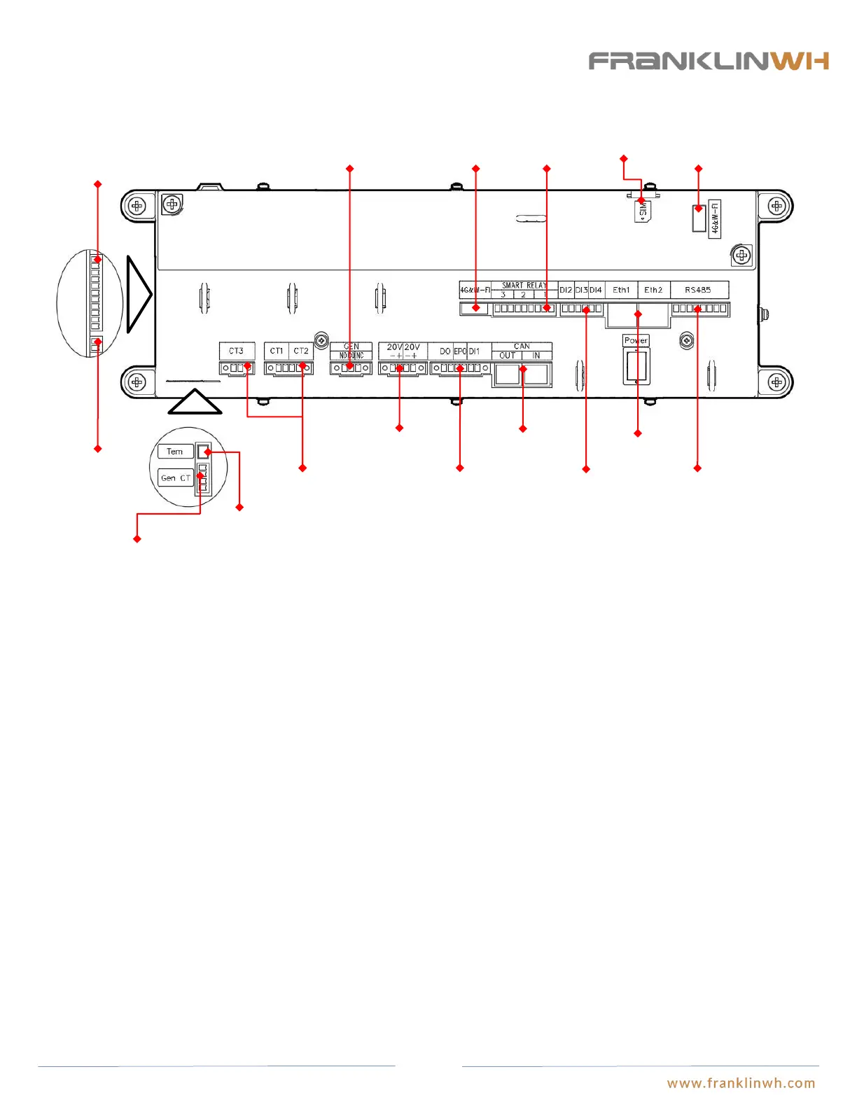
aGate
Purposes:
Power supply sampling terminal: Allows measurement of the aGate’s current and voltage and provides AC power to PCBA of EMS
module.
N bar: The Neutral bar input terminals.
Generator CT input terminal: Allows measurement of generator current data by external CT.
Temperature control sampling terminal: Signal input port for temperature control switch.
External CT input terminal: Input terminal for external CT to measure current information.
Generator contact interface: Generator data contact interface, where NO stands for constantly on, CO stands for the common ports, and
NC stands for constantly off.
20V DC input terminal: 20V DC power input to power the EMS control box.
Dry contact terminals: The contact terminals for on/off status of external signals. DI1, DI2, DI3 and DI4 are the input signal terminals,
DO is the output signal terminal (a current of no less than 10mA is required for DO relay to close reliably), and EPO is the emergency
stop input signal contact terminal.
CAN interface: the communication interface between aPower and aGate.
Smart loads terminals: The Smart Loads relay control interface.
4G&WIFI communication terminals: The connection interface between the control box and antenna box.
RS-485 communication port: The communication interface between the control box and smart meter.
SIM Card tray: Receptacle for SIM Card used for communication between EMS and user clients.
N bar
Power supply
sampling terminal
External CT
Input terminal
Generator
contact interface
20V DC input
terminal
Dry contact
terminal
CAN interface
Interface
4G&WIFI
communication
interface
Smart loads
Terminals
Dry contact
terminal
RJ-45 port
485
communication
interface
SIM card
Connector
4G&WIFI
communication
terminals
Temperature
control
terminal
Generator CT
input terminal
12