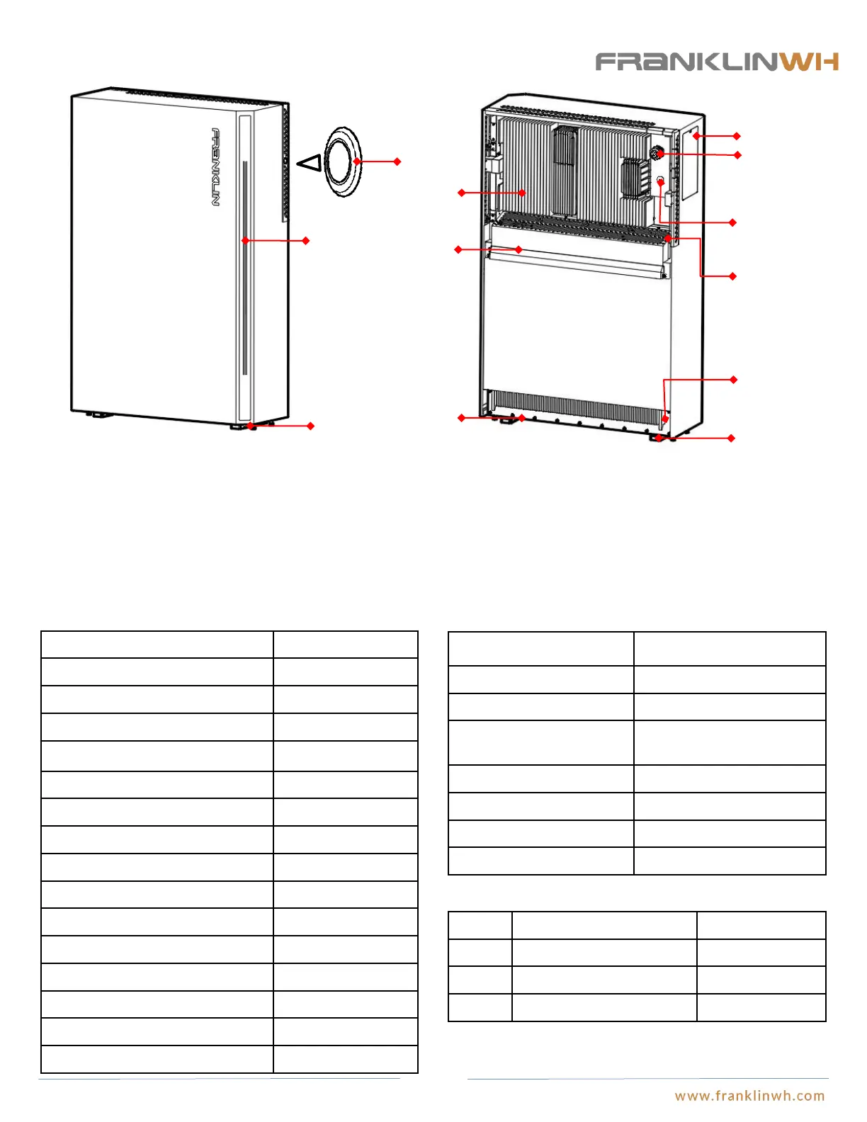
aPower
Switch
Power LED
1” water-proof lock
& charging cable
Heat sink
Heat sink
Snap joint 1
Leveling
screw
Supporting leg
Purposes:
DC Switch: Starts up or shuts off aPower.
Power LED: Turns on when aPower is started, to indicate the battery level.
Heat sink: Cools the components inside aPower.
Supporting leg: They support the aPower and keep it standing firmly.
Leveling screw: Helps keep the equipment well leveled where the floor is not
even.
Air outlet: Outlet where heat is discharged and must NOT be blocked.
Wiring compartment: Compartment that houses all electric terminals and
communication cable terminal connections.
Wiring closet
½” plug
Air outlet
Snap joint 2
Rated Input/Output Voltage
Rated Input/Output Current
Max.Continuous Input/Output Current
Battery Max. Short Circuit Current
Battery Rated Voltage/Capacity
750 mm×1150 mm×290 mm
(29.5in×45.3in×11.6in)
Operation Temperature Range
IP 67(Battery Pack&Inverter)
IP 56(Wiring)
Mechanical parameters
Shipping List
No. Item Quantity
1 Quick release grating 1 Set
2 Mounting bracket 1PCS
3 WAGO adapting cable 1PCS
Water-proof plug: Used to keep the charging cables in position. A 1” electrical
conduit may be used in place of the plug.
Charging cable: Used to charge aPower when it has a low battery level.
½” plug: ½” electric conduit may be run through the hole once plug is removed.
Snap joint 1: Snaps onto the mounting bracket to support the body of aPower.
Snap joint 2: Snaps onto the mounting bracket to support the body of aPower.
Electrical parameters description (see Appendix 1 for details)
8