Step 1: Site Planning
Plan installation position
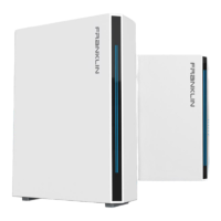
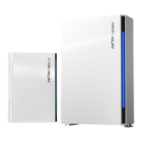
● Both aPower and aGate have special installation site requirements. aPower may be floor mounted against a wall or wall mounted.
For wall installation, aPower is mounted on the brackets to the wall to prevent it from falling off the wall. For floor mounted
installation, the mounting brackets are used to hold the aPower unit against the wall to protect aPower from tilting. All installation
configurations require aPower and aGate to be installed near or on walls.
● The selection of unit installation locations must account for wall embedded pipes and wires. Damage to the pipes and wires during
FHP installation may lead to property loss and/or personal injury.
● According to NFPA855, the aggregate rating amount within a dwelling, garage, or accessory structure shall not exceed the
following:
(1) 40 kWh within utility closets and storage or utility spaces
(2) 80 kWh in attached or detached garages and detached accessory structures
(3) 80 kWh on exterior walls
(4) 80 kWh in outdoor installations.
Therefore, if more than 6 aPowers are to be installed, the installation must follow the requirements of NFPA 855 Chapters 4-9 and may
proceed after approvals have been granted.
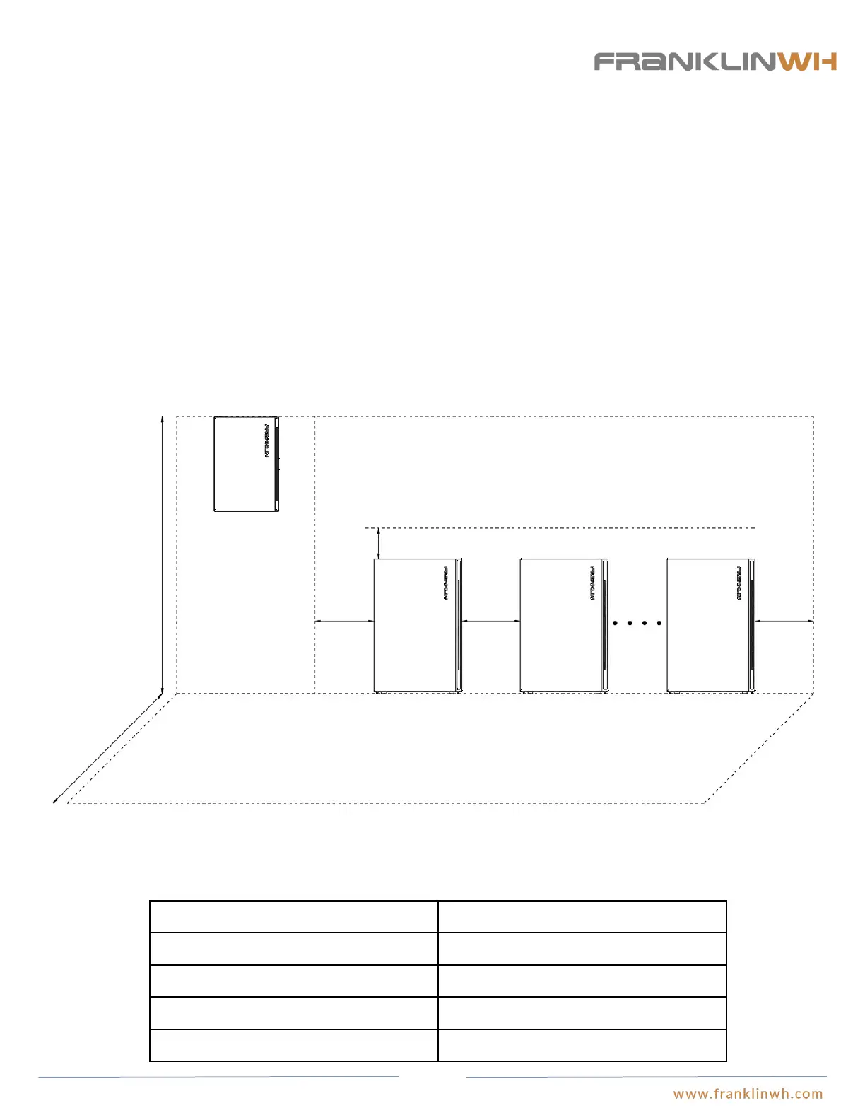
● The installation area for aPower and aGate must consider not only the space to be taken by the equipment, but also the necessary
space for wiring connections and the mandatory minimum clearances required for equipment to operate properly.
Data interchange equipment Maximum cable length
aPower and aGate 100 ft
aGate to Generator 100 ft
aGate to Router 300 ft
External CT 15 ft
≥6in ≥6in ≥6in
≥12in
≤80in
≥72in
aGate
aPower
Fork cart length
aPower
aPower
● FranklinWH system requires an internet connection. All signal transfers between aPower and aGate, the generator, and the router are
realized by CAN bus, network cables or other signal transmission cables. Long distances will likely adversely affect the quality and
speed of communication negatively impacting equipment operation. The installer or system designer will need to factor in the
recommended maximum cable lengths below when laying out the FWH installation.
Installation site 1
Installation site 2
16