Step 1: Site Planning
Plan the positions of inputs and outputs of the equipment
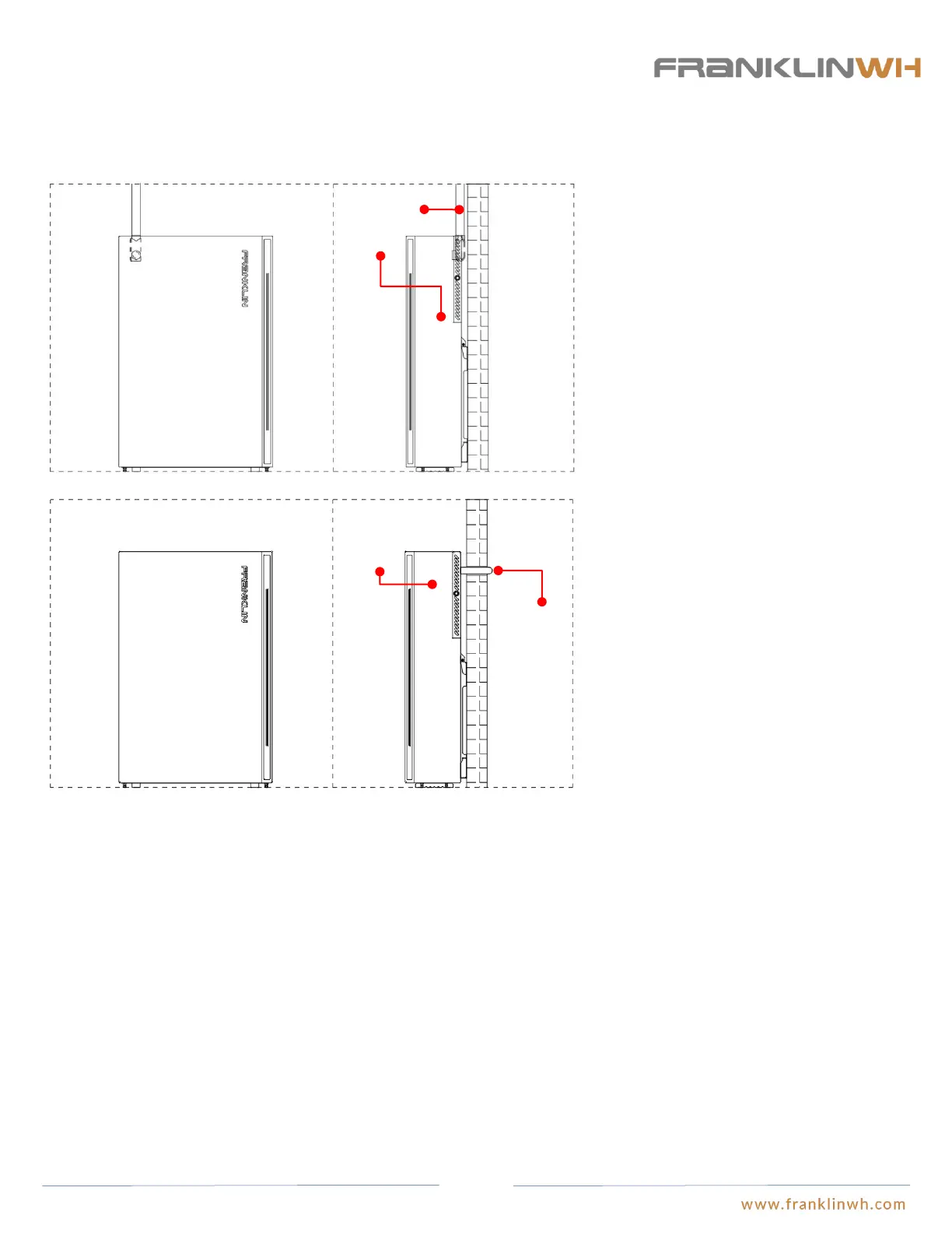
● The main cable connection for aPower is located at the rear of the unit case. The following scenarios offer variations on the cable
inlets and outlets of aPower to accommodate variations in the existing residential wiring layout.
Scenario 1: The cables passes through the electric
conduits and enters aPower from the same side as the
conduits. Gasketed pull boxes and sealing rings must be
used to ensure the tightness of the wiring closet. The
cable inlets on the wiring closet of aPower are 35mm
and 22mm in diameter respectively, and the pull boxes
that work with them have thread size of NPT 1” and
NPT1/2”. Reducing washers should be purchased as
necessary if diameters don’t match.
Scenario 2: The cables will connect to aPower from
inside the wall or through the wall though the electric
conduits. Sealing rings must be used. The cable inlets on
wiring closet of aPower are 35mm and 22mm in
diameter. A good sealing must be guaranteed between
the electric conduits and the wiring closet, which may be
realized by Hub or sealing rings, or caulk.
Run cables
into aPower
from inside
the wall or
through the
wall
Install aPower
on the front
exterior side of
wall
aPower and
electric conduits
share the same
side of the wall
17
Planning the Fire Control and Extinguishing System
● The selection and installation of fire control and extinguishing systems for residential power storage systems must comply with
the requirements of NFPA855 and local fire authorities.