Step 1: Site Planning
● The cable inlets and outlets are located on the four side panels of aGate: upper, lower, left and rear. The following scenarios
illustrate different configurations accounting for variations in the existing residential wiring layout.
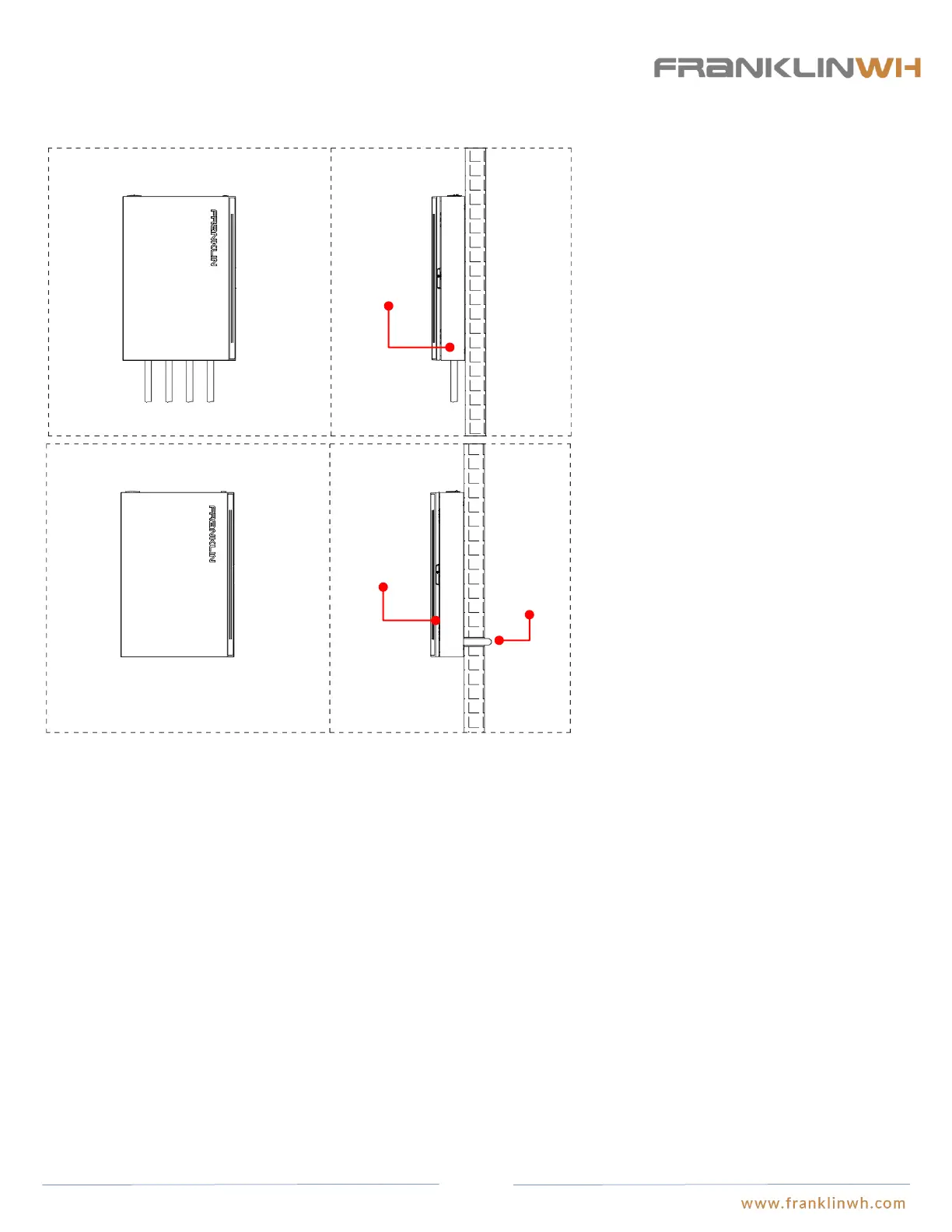
Scenario 1: Cables pass through the electric conduits and
enter aGate from the same side of the wall. Gasketed
junction boxes and conduit connections will be needed
to ensure the IP grade (water resistance) of aGate. The
electric conduit diameter varies by the types of conduits:
the knockout holes on the left and lower panel of aGate
are 35mm in diameter, while the knockout holes on the
upper panel are 63mm and 22mm in diameter. If the
knockout holes do not match the electric conduits in
size, additional reducing fittings will be needed to
achieve the required IP grade. If aGate is installed
outdoors, the electric conduits attach to aGate through
the cable inlet on the upper panel, and water-proof
sealant or caulk should be used at each connection of the
reducing fitting, junction box, electric conduit, and
aGate, in order to enhance the watertightness.
Scenario 2: Cables are run in electric conduits and enter
aGate from inside the wall or through the wall: in this
case, gaskets will be needed to ensure the IP grade
(water tightness) of aGate. The electric conduit diameter
varies by the types of conduits: the knockout holes on
the left and lower panel of aGate are 35mm in diameter,
while the knockout holes on the upper panel are 63mm
and 22mm in diameter. If the knockout holes do not
match the electric conduits in Hub diameter, additional
reducing fittings will be needed to achieve the required
IP grade. If aGate is installed outdoors, the electric
conduits connect to aGate through the cable inlet on the
upper panel. Water-proof sealant or caulk should be used
between the reducing fitting, junction box, electric
conduit, and aGate, in order to enhance the
watertightness.
Run cables
into aGate
from inside
the wall or
through the
wall
Install aGate on
the front exterior
side of wall
aGate and electric
conduits share the
same side of the
wall.
Planning protection for aGate’s input connections
● aGate serves as the entrance to the Franklin Home Power system. Installation of proper lightning protection systems are required
before the input end of aGate. Over current protection measures are required to be installed before the aGate inputs or inside the
aGate. A breaker of 100A to 200A may be installed at the grid input connection and the fuel generator input connection. Please refer
to Step 6 of this Guide for the recommended models of breakers inside aGate.
Planning the types, sizes and routes of cable and electric conduits
● Please refer to Step 8 of this Guide for recommended cable types and wire diameters electric connections and communication
connections between aGate and aGate and between aGate and the residence’s power distribution system.
● The current carrying capacity of cables needs to be reduced as wires travel longer distances through electric conduits. Please refer
to the applicable information if Appendix B to NFPA 70.
● The relationship between wire diameters, cable numbers, and inner diameters of conduits should be taken into general
consideration as cables run through the electrical conduits. Please refer to Appendix C to NFPA 70 for the list of maximum numbers
of cables of the same size in the electric conduits and pipelines.
● The type of electric conduits depend on the installation type: indoor or outdoor. IMC, EMT and other thin-wall metal conduits are
recommended in case of indoor installation. These two types of conduits are cost effective and provides excellent anti-
electromagnetic interference and are easy to shape and to joint. In outdoor installation, GRC and RMC thick-wall conduits are
recommended, because they can provide effective mechanical protection and good tightness at the conduit joints. Thick-wall conduits
have a reduced flexibility disadvantage which makes bending and jointing very difficult.
FCC Requirements
● See Appendix 1 for the applicable FCC Requirements. Installer informs user of the contents in Appendix 1.
18