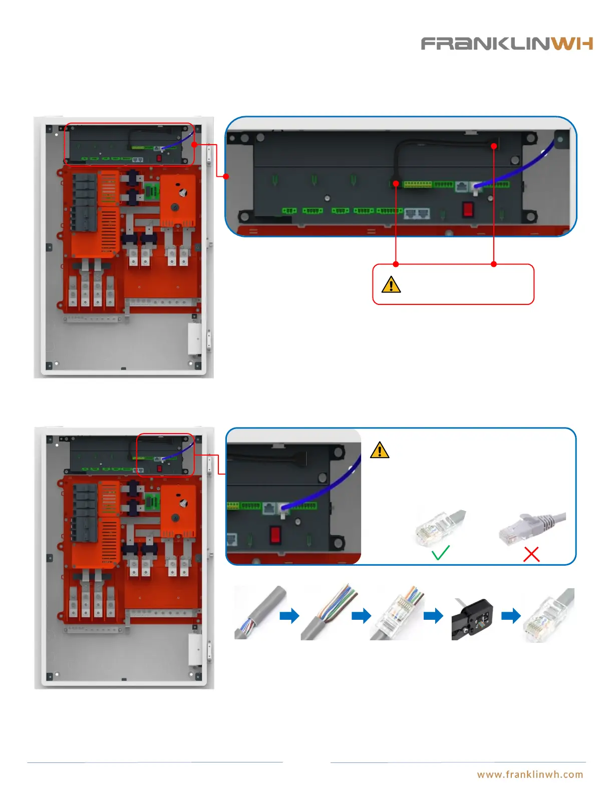
Step 7: Communication Wiring
Connect aGate to a residence’s network
Wire the 4G&Wi-Fi communication module in aGate
4G&Wi-Fi
Eth 2
The aGate cannot be
activated if this step is not
finished.
4G&Wi-Fi
Insert the USB connector from the antenna module into the 4G&Wi-Fi ports on the EMS module and the antenna module to enable
wireless connection optionality.
The network cable should be made on site
using RJ45 connectors and cables, while
the ready-made network cable should not
be used, or otherwise the bending of
cables inside aGate may take too much
space that the internal panel cannot be
closed.
To ensure the reliability of remote communication, it is recommended to insert the residence’s network cable with Internet connection to the “Eth 2” port of EMS
module to enable the remote communication function.
① Remove the insulation jacket from the cable.
② Fan out the wires in the order of 568B (white/orange, solid orange, white/green, solid blue,
white/blue, solid green, white/brown, solid brown).
③ Insert the wires into the connector.
④ Crimp the connector using a crimping tool.
⑤ The cable is ready.
① ② ③ ④ ⑤
RJ-45 Connector:
50