Step 7: Communication Wiring
Network cable connection between aGate and aPower (if distance between aPower and aGate is less than
100 ft)
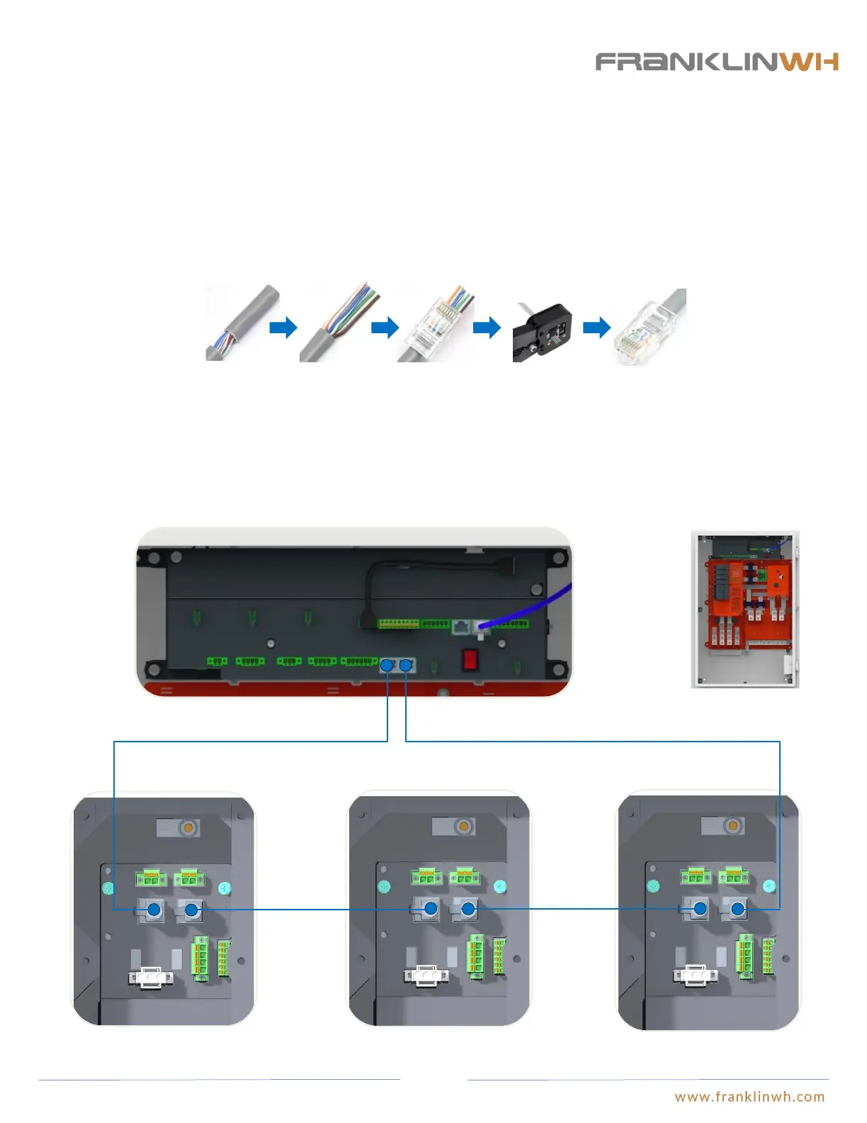
When the communication cable length between aPower and aGate is less than 100ft, connecting via network cabling is acceptable.
The network cable should form a loop between aPower and aGate. If multiple aPowers are installed, the network cables should
connected in tandem or “daisy chained.” Insert the network cable between aGate and aPower 1 into the “CAN OUT” port of aGate
and the “CAN IN” port of aPower 1; insert the network cable between aPower 1 and aPower 2 into the “CAN OUT” port of aPower
1 and the “CAN IN” port of aPower 2; insert the network cable between aPower 2 and aPower3 into the “CAN OUT” port of
aPower 2 and the “CAN IN” port of aPower 3, so on and so forth until the connection between aPower N and aGate, where the
network cable should be inserted into the “CAN OUT” port of aPower N and the “CAN IN” port of aGate.
CAN IN
CAN OUTCAN IN
CAN OUT
CAN IN
CAN OUT
CAN OUT
CAN IN
aGate EMS
aPower 1 wiring closet aPower 2 wiring closet aPower N wiring closet
① Run the network cable through the electric conduit, remove the insulation jacket from both ends.
The color of network cable should comply with the local regulations.
② Fan out the wires in the order of 568B (white/orange, solid orange, white/green, solid blue,
white/blue, solid green, white/brown, solid brown).
③ Insert the wires into the connector.
④ Crimp the connector using a crimping tool.
⑤ The cable is ready.
① ② ③ ④ ⑤
RJ-45 Connector:
51