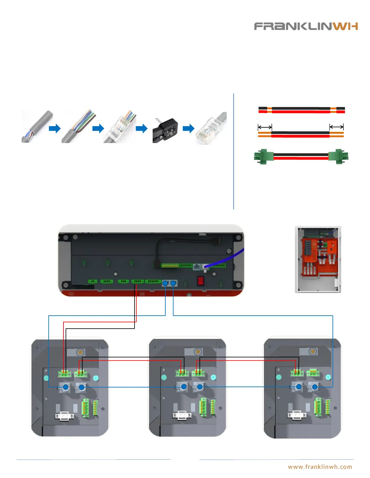
Step 7: Communication Wiring
Communication cable connections between aPower and aGate (if distance between aPower and aGate is longer
than 100ft)
CAN in
CAN out
CAN OUT CAN IN
aGate EMS
aPower 1 wiring closet aPower 2 wiring closet aPower N wiring closet
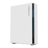
① Run the network cable through the electric conduit, remove the insulation jacket from both ends. The color of
network cable should comply with the local regulations.
② Fan out the wires in the order of 568B (white/orange, solid orange, white/green, solid blue, white/blue, solid
green, white/brown, solid brown).
③ Insert the wires into the connector.
④ Crimp the connector using a crimping tool.
⑤ The cable is ready.
① ② ③ ④ ⑤
RJ-45 Connector:
Both network cable connection and 20V power supply must be used in conjunction when the communication cable length between aPower and aGate is longer than 100ft. The network cable
should form a loop between aPower and aGate similar to installations with distances less than 100ft. Insert the network cable between aGate and aPower 1 into the “CAN OUT” port of
aGate and the “CAN IN” port of aPower 1; insert the network cable between aPower 1 and aPower 2 into the “CAN OUT” port of aPower 1 and the “CAN IN” port of aPower 2; insert the
network cable between aPower 2 and aPower3 into the “CAN OUT” port of aPower 2 and the “CAN IN” port of aPower 3, so on and so forth until the connection between aPower N and
aGate, where the network cable should be inserted into the “CAN OUT” port of aPower N and the “CAN IN” port of aGate. The 20V power supply should be wired in series.
-+
Vcc+ GND
20V power cable preparation:
①
②
1/2in
1/2in
① Run the 20V power cable of 18AWG~16AWG through
the electric conduit. Refer to the local regulations for the
cable colors.
② Remove the insulation jacket on both ends by 1/2 in.
③ Connect the wires to the corresponding terminals.
③
Vcc+ GND
CAN in
CAN out
Vcc+ GND
Vcc+ GND
CAN in
CAN out
Vcc+ GND
Vcc+ GND
52