The FRC PRO-S Pressure Governor is a sophisticated, microprocessor-controlled device designed to manage pump discharge pressure or engine RPM in various engine types. It offers automatic regulation, manual control, and field-programmable presets, making it a versatile tool for maintaining steady operational parameters.
Function Description:
The PRO-S operates in two primary modes: pressure mode and RPM mode.
In pressure mode, the governor maintains a constant pump discharge pressure. It continuously monitors the discharge pressure and compares it to a selected pressure setting. The engine RPM is then automatically adjusted to ensure the discharge pressure remains at the set value. This mode is ideal for applications requiring consistent water pressure, such as firefighting.
In RPM mode, the PRO-S maintains a constant engine RPM. While in this mode, the pump discharge pressure is monitored, and as a safety feature, any increase in pressure is limited to 30 PSI. If the discharge pressure rises by 30 PSI, the governor automatically lowers the engine RPM to reduce the pressure surge, preventing potential damage or unsafe conditions. The RPM LED will blink when the PRO-S sets a lower RPM, and pressing any button will stop the blinking.
A key feature is the seamless transition between modes; no variation in discharge pressure or RPM occurs when switching. When changing to RPM mode, the RPM setting will default to the RPM the pump was operating at in pressure mode. Conversely, when switching to pressure mode, the pressure setting will be the pressure the pump was operating at in RPM mode.
The device also incorporates a "No or Low Supply Water" detection system. In pressure mode, if the discharge pressure drops below 45 PSI but stays above 15 PSI, the PRO-S initiates a low water cycle. It sets the engine to 1100 RPM for 7 seconds (30 seconds for PRO-S 3 models). If the pressure does not rise above 45 PSI within this time, the engine is set to idle RPM for another 7 seconds. This cycle repeats as long as the discharge pressure remains between 15 and 45 PSI. If the discharge pressure falls below 15 PSI, the engine goes to idle, and the SETTING display shows the selected setting. Normal control resumes when the discharge pressure rises above 45 PSI.
For opening/closing discharge valves, the PRO-S maintains the pressure setting by automatically adjusting engine RPM to compensate for changes in water supply and demand, provided there is sufficient water.
Important Technical Specifications:
The PRO-S is available in various models, each tailored to specific engine types.
- PRO-S 1: Cummins (IS Series)
- PRO-S 2: Detroit Diesel (Series 50 and 60)
- PRO-S 3: Non-Electronic diesel and gasoline engines
- PRO-S 4: Navistar and Detroit Diesel (Series 40)
- PRO-S 5: Caterpillar
- PRO-S 6: Ford
- PRO-S 7: Mack
- PRO-S 8: Scania
- PRO-S 10: Mercedes
Common specifications across models include:
- Supply Voltage: 12 VDC (24 VDC optional)
- Supply Current: 1.0 AMP (3.0 AMP for PRO-S 3)
- Response (Idle to full governed speed): 5 SEC (30 SEC for PRO-S 3)
- Recovery (After open or close of valve): 1.5 SEC
- Datalink Protocol: J1587 (for electronic engines)
RPM Calibration varies by model:
- Manual: PRO-S 3, PRO-S 6, PRO-S 8
- None: PRO-S 1, PRO-S 2, PRO-S 4, PRO-S 5, PRO-S 7, PRO-S 10
The Pressure Transducer (PRO31PT2) has the following specifications:
- Pressure Range: 0 - 300 PSI
- Proof Pressure: 800 PSI
- Excitation Voltage: 5 VDC
- Output Voltage: 0.5 - 4.75 VDC (proportional to pressure)
Usage Features:
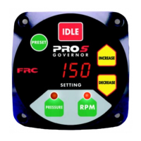
The control module features push-button electronic controls, LED indicators, and a digital display for easy operation.
- PRESET Button: Sets pump pressure or engine RPM to a preprogrammed value and is used for programming preset values.
- IDLE Button: Immediately sets the engine to idle RPM, useful for emergencies or normal shutdown.
- SETTING Display: Shows diagnostic error codes, "IdLE" for engine idle, or the current pressure/RPM setting with daylight-bright digits.
- INCREASE/DECREASE Buttons: Adjust pressure or RPM settings. Momentary presses change by 1 PSI or 10 RPM. Holding for >2 seconds changes by 5 PSI/50 RPM (twice) then 10 PSI/100 RPM until released.
- RPM Button: Selects RPM mode. The red RPM LED indicates operation in RPM mode.
- PRESSURE Button: Selects pressure mode. The amber PRESSURE LED indicates operation in pressure mode.
Other usage features include:
- Power-up in pressure mode.
- Manual control of pressure or engine RPM settings.
- Field-programmable presets.
- Diagnostic capabilities.
- Recognition of no water condition with automatic response.
- Interlock signal recognition.
- Return to engine idle with a single button push.
- Optional 24 VDC and KPa units.
Maintenance Features:
The PRO-S includes diagnostic capabilities to aid in troubleshooting. The SETTING display will show error codes (E1-E7) corresponding to specific problems and probable causes, such as:
- E1 (No communication on datalink): Could be due to no voltage at interlock input, disconnected/incorrectly wired datalink cable, or broken wire/bad connector contact.
- E2 (Bad data on datalink): Often caused by noise interference (radio frequency or electrical).
- E3 (RPM data not detected): For electronic engines, datalink cable issues or engine not running/ignition key on. For non-electronic engines, broken wire/bad connector contact on alternator cable.
- E4 (Cannot transmit over datalink): No voltage at interlock input, internal datalink problem, or datalink shorted.
- E5 (Discharge pressure transducer not detected): Transducer cable issues, broken wire/bad connector, or defective transducer.
- E7 (Not able to raise pump pressure from idle to set pressure): Low supply water, intake line problem, valve closed, pump not primed, or defective pressure transducer.
Installation and Calibration:
- Control Module: Waterproof, dimensions 4.25"H x 4.25"W x 3.5"D (4.5"D for non-electronic and 24 VDC units). Mount close to engine warning indicators.
- Pressure Transducer: Mounts on the pump discharge manifold, preferably before a check valve. Install upright to allow water drainage.
- Throttle Servomotor (Non-Electronic Engines Only): Provides mechanical connection to the engine throttle. Ensure a 2-inch stroke at the fuel control arm to minimize engine oscillations.
- High Idle Kit (Optional): Includes a DPDT switch, 2500 ohm potentiometer, indicator light, two diodes, and a cable. The potentiometer is adjusted during calibration to set the high idle RPM.
- RPM Calibration (PRO-S 3, 6, and 8): Requires a reference tachometer. The procedure involves pressing IDLE, RPM, and PRESET buttons in sequence to set the engine RPM to 1200 RPM using INCREASE/DECREASE buttons.
- High Idle Option Calibration: Adjust the 2500 ohm potentiometer with a small screwdriver while the high idle switch is ON and monitoring engine speed with a tachometer.
- 3rd Gear Lock-up RPM Calibration (Ford 6.0L): Factory set at 1200 RPM. Procedure involves pressing IDLE, RPM, and PRESET buttons to change the programmed lock-up RPM.
Wiring:
Detailed schematics and wiring diagrams are provided for various engine types and components, including power supply, high idle, pressure transducer, and OEM connectors (Deutsch, Packard). Flyback diodes are recommended for inductive loads sharing a common power source/ground with the governor to prevent damage.