PRO-S Rev1104
23
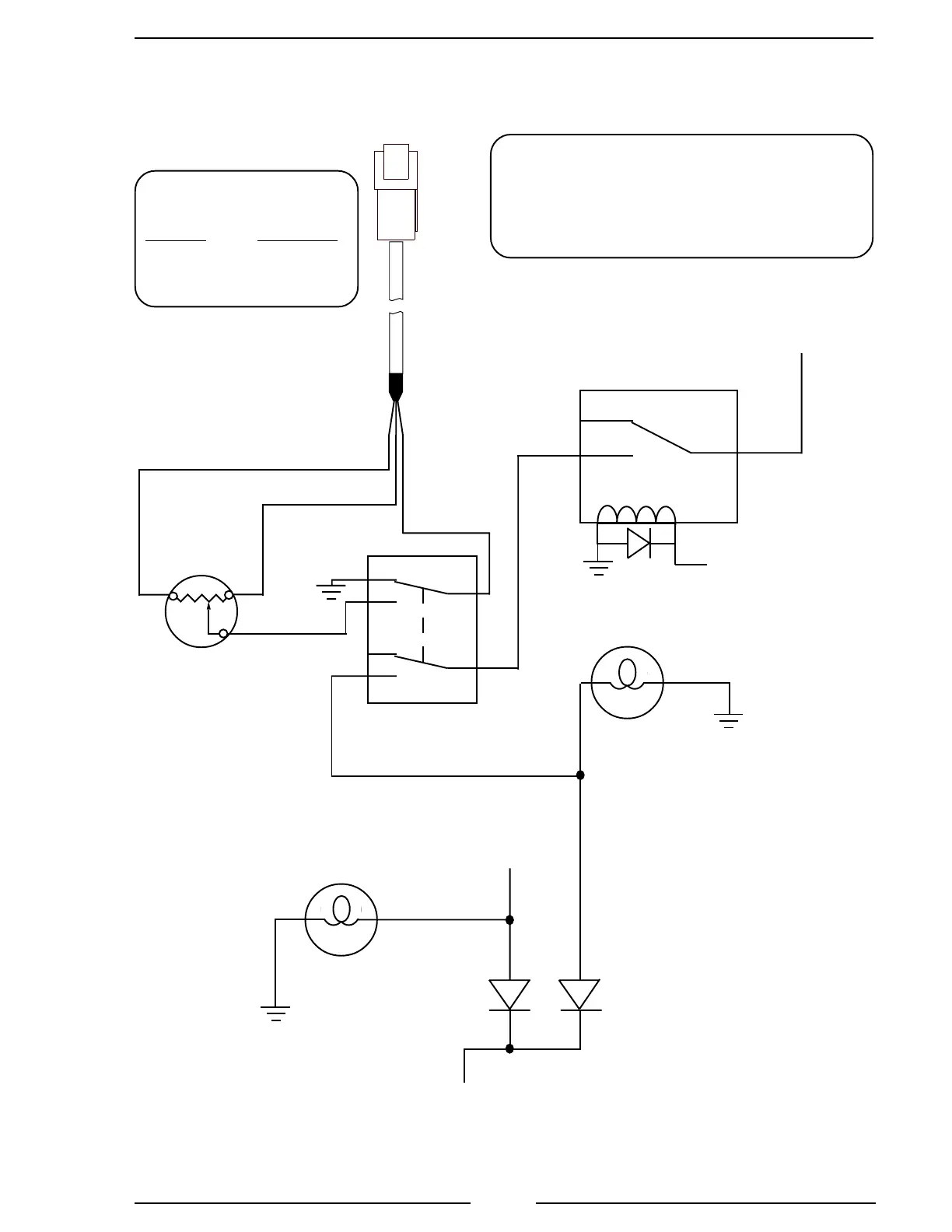
Figure 7. Optional High Idle Schematic
High Idle
From Control Module
High Idle 3-Pin
Deutsch Connector
Black
Red
High Idle
2500 Ohm
Potentiometer
High Idle
Indicator
Light
High Idle ON/OFF
Switch
White
From Parking
Brake
Diodes
(IN4002 or
equivalent)
NC
C
From
Transmission
Neutral 12VDC
From
Pump Engaged
12VDC
To Control Module White
Interlock Wire
(Located in power cable.)
Pump Engaged
Indicator Light
GND
NC
NO
NC
NO
NO
C
C
GND
GND
GND
High Idle
Cable
High Idle Cable
Connector
Pin/Wire Description
A/Red +5 VDC
B/Black Ground
C/White Signal
Note: If the optional remote high idle kit is
being installed, the high idle cap must be
removed. (It is installed on the end of the
control module high idle cable and has a
jumper wire between pins B and C. )
ON
OFF
FRC kit part number
PRO-38H.