Part number 550-142-950/0122
115
FreeStyle
®
series
2
wall mount gas-fired water boiler – boiler manual
38 Maintenance (continued)
Procedure for Cleaning of Internal Heat
Exchanger Circuit
is procedure is intended as a guideline for a correct restora-
tion of the functionality of the boiler as a result of operation with
untreated water, very hard water feeding conditions, debris, lime
scale, sludge, metal oxides and, in low temperature systems, also
biomass in the heat exchanger water circuit.
y Carefully read and follow the instructions below.
y Cleaning and maintenance must be carried out by profes-
sionally qualied personnel, in compliance with the current
regulations and according to the manufacturer’s instructions.
Do not carry out any operation on the sealed control parts.
y Before carrying out any cleaning or maintenance operation,
disconnect the unit from the electrical power supply using
the switch and/or the special cut-o devices.
y e disposal of chemicals and residues of cleaning should
be carried out in an appropriate manner, in accordance with
current standards.
y Before installation of the boiler, carefully ush all the pipes of
the system to remove residues or impurities that could aect
the proper operation of the unit. Use chemical conditioners
and cleaners listed on pages 77 and 121.
y If it is necessary a cleaning of the heat exchanger circuit to
recovery the functionality of the boiler as a result of operation
with untreated water, very hard water feeding conditions,
sludge, metal oxides and, in low temperature systems, also
biomass in the heat exchanger water circuit, is allowed the
use of chemical products for the cleaning, if and only if the
manufacturer of these uids provides a guarantee which
ensures that its products are suitable for use and cause no
damage to the heat exchanger or other components and / or
materials of the boiler and system.
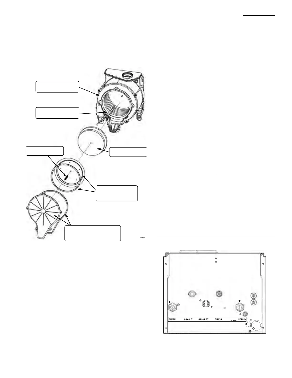
Ignitor
Refractory
Heat exchanger cover
plate and gasket
Burner and
burner gasket
Heat Exchanger
Spring
Figure 153 Heat exchanger components
Figure 154 Heat exchanger components (Combi-80/120
shown)
1 System supply
2 Domestic hot water outlet
3 Gas inlet
4 Domestic cold water inlet
5 System return
6 Plastic screw, Combi
pressure relief
1
2
3
4
5
6