Part number 550-142-950/0122
119
FreeStyle
®
series
2
wall mount gas-fired water boiler – boiler manual
38 Maintenance (continued)
5. e treatment time must be chosen according to the
amount of scale deposits present in the exchanger and
however such time must always be less than the maxi-
mum treatment time specied by the manufacturer on
the product data sheet.
6. At the end of the cleaning cycle recover the chemical
product in appropriate containers for disposal.
7. Perform a washing bath with potable water in order to
remove the chemical product still present within the
coils of the heat exchanger, recovering the liquid in
suitable containers for disposal.
8. Repeat the washing with water more than once if neces-
sary.
9. e cleaned brazed plate heat exchanger can now be
installed.
e brazed plate heat exchanger must be
reinstalled in the same orientation.
e direction of arrows on heat exchanger.
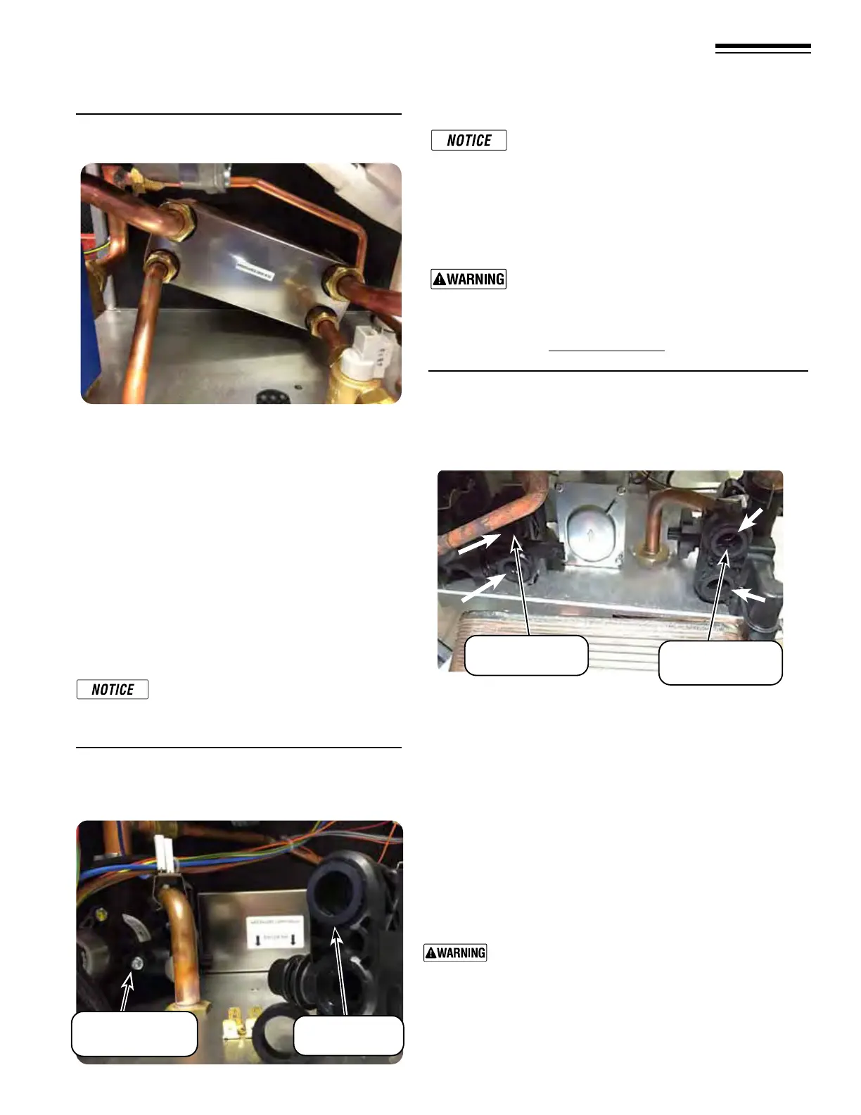
Combi 80/120 at plate heat exchanger
reinstalled
e four (4) new gaskets must be placed in the
DHW inlet and DHW return plate connections to
seal brazed plate heat exchanger.
1. Slide the brazed plate heat exchanger into rear of enclosure
(orientation arrows pointing down).
2. Li brazed plate heat exchanger slightly up and align with DHW
connections, reinstall the two (2) Phillips head screws, tighten
securely. (Torque to 3.3 lb-. +/- 0.37 lb-.)
When re-installing components, make sure gaskets
are in good condition and properly aligned before
tightening screws.
3. Be sure the pressure relief (plastic) screw has been made tight,
Location(6), see Figure156,page118.
Figure 160 Removal of at plate heat exchanger by
loosening the four ttings. Combi-155
DHW returns
(diverter valve)
DHW inlet
DHW Outlet
(diverter valve)
DHW Inlet
Combi 155 at plate heat exchanger reinstalled
1. For the Combi-155, slide the cleaned brazed plate heat exchanger
into rear of enclosure (orientation as shown in Figure160).
2. Li brazed plate heat exchanger slightly up and align with DHW
connections, reinstall the ttings. e four (4) gaskets must be
placed in the DHW inlet and DHW return plate connections to
seal brazed plate heat exchanger.
1. Reassemble boiler components check seals for any leaks.
2. Open the valve of cold water inlet placed before the boiler inlet.
Run water until all air is purged from both the brazed plate heat
exchanger and the primary heat exchanger.
3. At initial ll and during boiler startup and testing, check system
thoroughly for any leaks. Repair all leaks before proceeding further.
Eliminate all system leaks. Continual fresh make up
water will reduce boiler life. Minerals can build up in the
heat exchanger, reducing heat transfer, overheating heat
exchanger, and causing heat exchanger failure.
4. Reconnect the unit to the electrical power supply using the switch
and/or the special cut-o devices and turn it ON.
5. Check the correct operation of the boiler and functionality of
production of domestic hot water.
Figure 161 Reinstall the four (4) gaskets into DHW
inlets and returns(components removed
to show gasket locations, for illustrating
purposes) (Combi Only 80/120 shown)
Figure 162 Gaskets being placed into DHW inlet and DHW
return plate connections. (Combi Only 80/120)
(Shown from rear view of enclosure showing all
four (4) water connections.)
(Back panel removed for illustration purposes).


 To Next Page