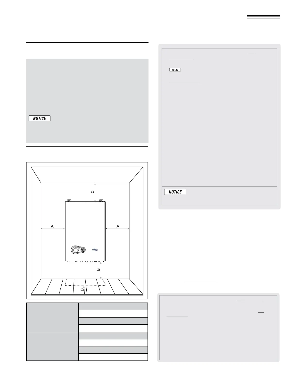
Figure 1 REQUIRED minimum clearances
(
all dimensions are in inches)
Part number 550-142-950/0122
5
FreeStyle
®
series
2
wall mount gas-fired water boiler – boiler manual
2 Prepare boiler location continued
Provide clearances from
combustible materials — REQUIRED
1. See Figure1 for REQUIRED minimum clearances. ALL
installation must provide at least these minimums.
2. Hot water pipes — at least ½” from combustible materials.
3. Vent pipe — at least
3/16” from combustible materials.
4. See Figure1 for service clearance minimums.
If the unit is enclosed in a cabinet or mounted
alongside, a space must be provided for remov-
ing the casing and for normal maintenance
operations. e minimum measurements to be
respected are given in Figure1.
Provide clearances for service
access — RECOMMENDED
1. See the table in Figure1 for recommended service clearances.
2. If you do not provide minimum service clearances shown, it
might not be possible to service the boiler without removing
it from the space.
3. Clearance D, Figure1 allows for the installation of piping as
shown in Figure5,page9, plus a union, close nipple and
elbow.
Clearances
A Provide combustion air/ventilation openings per Fig-
ure23,page20 or as otherwise directed in this manual or by
applicable codes.
If the installation does not provide the minimum clear-
ances, then the enclosure MUST HAVE air openings located per
Figure23,page20. Each of these air openings must have free area
of at least 1square inch per 1,000 MBH of boiler input.
B Le side clearance to combustibles = 1.0 inches minimum
C Top of boiler clearance to combustibles = 12.0 inches minimum
D Right side clearance to combustibles = 1.0 inches minimum
E Bottom of boiler clearance to combustibles = 12 inches minimum
(must be 18inches above oor for garage installations)
F Clearance in front of the boiler = 12.0 inches, but 36 inches
minimum required for service
H Vent pipe must be minimum 3/16 inch from combustibles. Open-
ing in combustible wall, oor, ceiling or roof must be 3/8” larger
than ue pipe diameter, tted with galvanized steel thimble, or
larger if required by codes or as specied by vent pipe manufac-
turer.
ADDITIONAL service clearance may be
needed, depending on how piping is routed
to the boiler.
A Provide combustion air/ventilation openings per Figure23,page20 or as
otherwise directed in this manual or by applicable codes. NOTE: If the
installation does not provide the minimum clearances in this illustration,
then the enclosure must have air openings located and sized per Fig-
ure23,page20.
B Le side service clearance = 36 inches minimum
C Service clearance above top of boiler = 24 inches minimum
D Right side service clearance = 24 inches minimum
E Service clearance below the boiler = 36 inches minimum
F Service clearance in front of the boiler = 36 inches minimum
Minimum
required
for
Combustion
A Minimum 1.00”
B Minimum 12.00”
C Minimum 12.00”
D Minimum 12.00”
Recommended
for
Service
A Minimum 36.00”
B Minimum 36.00”
C Minimum 24.00”
D Minimum 36.00”