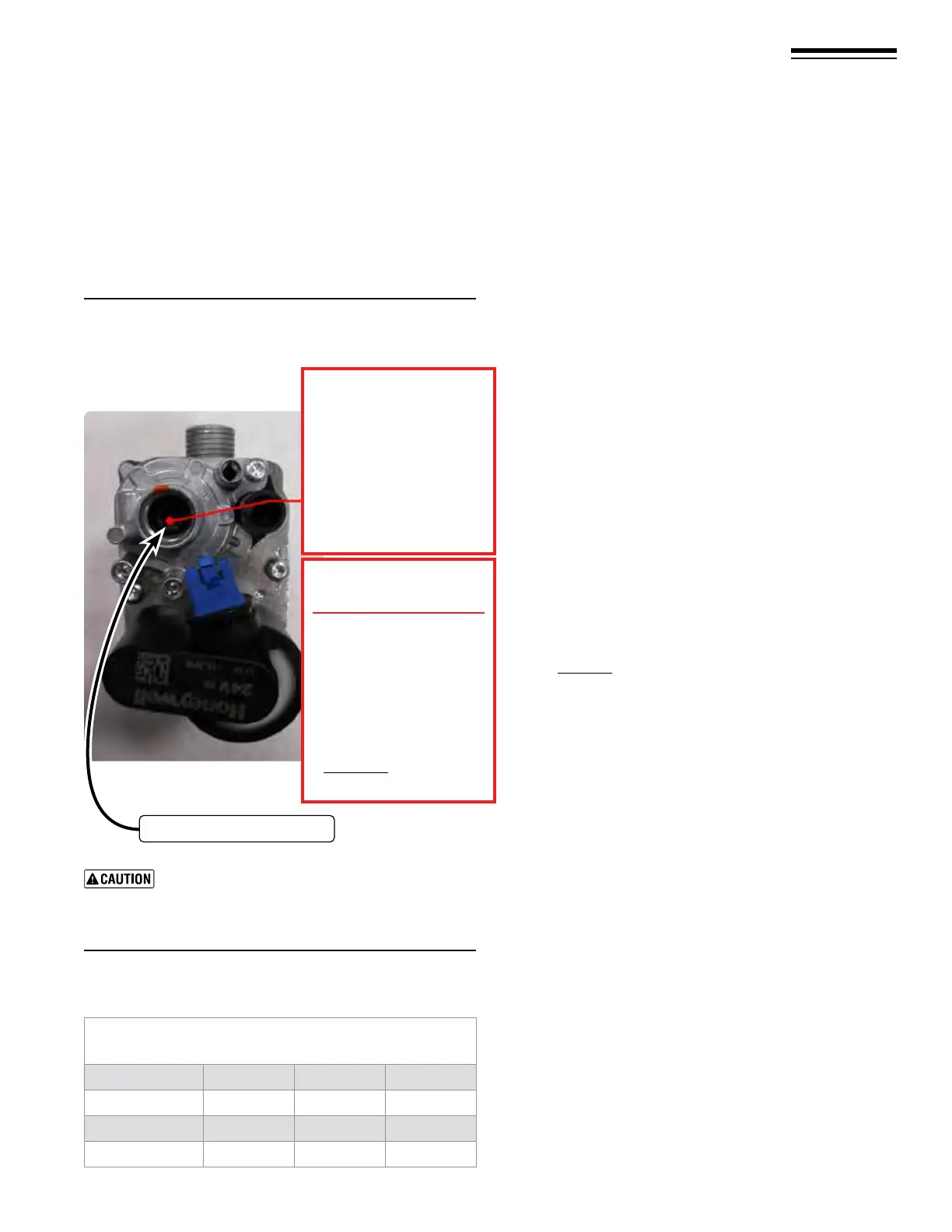
Figure 109 Offset adjustment screw ––
(ONLY for use by a qualied technician, using
calibrated combustion test instruments).
Part number 550-142-950/0122
83
FreeStyle
®
series
2
wall mount gas-fired water boiler – boiler manual
Natural Gas/LP Acceptable Combustion Range
Minimum Rate after 10 minutes from cold
Boiler Model CO/(PPM) CO
2
NG % CO
2
LP %
FS-80
20 8.0
–
9.0 9.0
–
9.8
FS-120
20 8.0
–
9.0 9.0
–
9.8
FS-155
7 8.0
–
9.0 9.0
–
9.8
At Minimum Rate:
1. Adjust the boiler to minimum output and allow the boiler
to stabilize.
2. Now adjust the oset pressure setting (Figure109 - screw B)
Torx (T-40 male driver) until the CO
2
is at the correct SET-
TING LEVEL (see Figure110), conrm that the CO/CO
2
ratio is within limits (clockwise to increase gas).
33 Startup — nal checks (continued)
Re-check the Maximum and Minimum
Rate
3. Turn o the boiler and then turn it back on and put in Test
Mode at maximum for 1 minute, then reduce ring rate/
high re for 1 minutes. Reduce to minimum and re-check
the minimum rate output ensuring the CO
2
setting level has
remained unchanged and conrm that the CO/CO
2
ratio is
within limits.
4. In the event that the CO
2
setting level with an acceptable
CO/CO
2
ratio cannot be obtained please contact your
Williamson-ermoo representative.
5. Should you require any assistance during the set up pro-
cedure contact your Williamson-ermoo representative
if the problem cannot be addressed with the information
provided in this manual.
Check Heat exchanger and vent seals
1. Operate the boiler on HIGH re.
2. A leak would appear as vapor on the surface of the mirror.
3. If there is any indication of a leak at any joint, immediately
shut down the boiler.
a. If possible, tighten the retaining screws or nuts (without
over-tightening).
b. If this does not correct the problem, disassemble the
components where the leak appeared. Use the proce-
dures given in the Maintenance section, starting on
page111.
c. When disassembling components, inspect gaskets to see
if there is damage. Replace any damaged gasket.
d. Contact your Williamson-ermoo representative if
the problem cannot be addressed with the information
provided in this manual.
Check ignition system safety shutoff device
1. Aer the boiler has been installed, turn o the boiler.
2. Shut o the manual gas valve located on the gas line to cut
ow of fuel to the boiler.
3. Turn on the boiler. It will start to ignite and a “d3” code will
ash. Aer the “d3” code ash for some time the boiler will
go into a Lockout condition and a “A01” code will show in
the display. It means that the boiler tried to ignite without
success (code “d3”) for three (3) times and when into
Lockout mode(code “A01”). is means that the ignition
system safety device worked properly.
4. Open the manual gas valve located on the gas line to resume
fuel supply to the boiler.
5. Hit the “Reset” button once to Clear the Lockout code
“A01”.
Figure 110 Minimum rate combustion values –
measured values must be within the ranges
given below
Adjust in steps of no more than 1/8 of a turn and
wait 1 minute aer each adjustment to allow the
setting to stabilise. Turning the screw too far will
cause the adjustment to reverse behavior.
Offset Regulating screw
Test at MIN. Power 00%
Turn clockwise (open gas)
for “MAX gas ow”
Turn counter-clockwise
(close gas)
for “MIN gas ow”
Offset adjustment B
Rough start point
For LP Start up ONLY
Adjust gas valve
LOW FIRE
screw on le with
Allen wrench
turn
Counter-Clock wise
⅛ - ¼ turn.
Final Combustion values
MUST BE checked with
Combustion Analyzer.