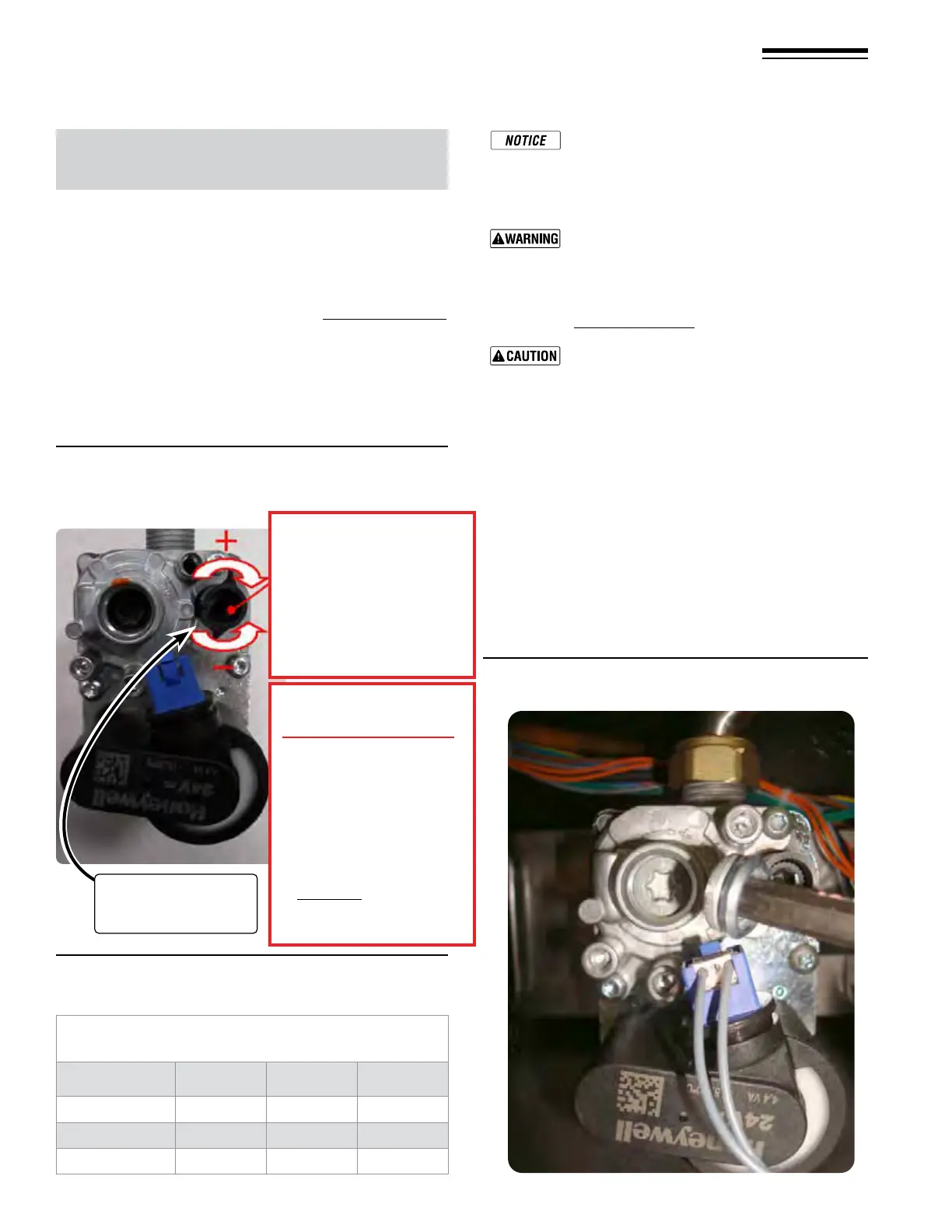
Figure 106 Throttle adjustment screw ––
(ONLY for use by a qualied technician, using
calibrated combustion test instruments).
Part number 550-142-950/0122
82
FreeStyle
®
series
2
wall mount gas-fired water boiler – boiler manual
33 Startup — nal checks (continued)
Figure 107 Maximum rate combustion values –
measured values must be within the ranges
given below
Using a combustion analyzer check the CO
2
values at low and high re. It should be within
values from the table in Figure107. e dier-
ence of CO
2
from high re to low re should
NEVER be below 0.2% or above 1%.
DO NOT attempt to adjust the throttle screw
unless by a qualied technician, and with the
use of calibrated combustion test instruments.
Adjust the throttle screw only as needed to meet
the combustion values given in Figure107 and
Figure110,page83.
Adjust in steps of no more than 1/8 of a turn and
wait 1 minute aer each adjustment to allow the
setting to stabilise. Turning the screw too far will
cause the adjustment to reverse behavior.
4. In the event that the CO
2
setting level with an acceptable
CO/CO
2
ratio cannot be obtained please contact your
Williamson-ermoo representative.
5. Should you require any assistance during the set up pro-
cedure contact your Williamson-ermoo representative
if the problem cannot be addressed with the information
provided in this manual.
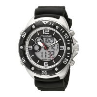
6. Remove T-40 cap, see Figure108, below, for Oset screw
adjustment.
Natural Gas/LP Acceptable Combustion Range
Maximum Rate after 10 minutes from cold
Boiler Model CO/(PPM) CO
2
NG % CO
2
LP %
FS-80
110 9.0
–
9.5 10.2
–
10.7
FS-120
110 9.0
–
9.5 10.2
–
10.7
FS-155
120 9.0
–
9.5 10.2
–
10.7
Setting the Air/Gas Ratio valve
ere are two adjustments possible on the air/gas ratio valve,
the throttle setting at Maximum rate and the oset setting at
Minimum rate. If either setting is adjusted the combustion values
must be rechecked at both rates.
At Maximum Rate:
1. Adjust the boiler to maximum rate in Figure104,page79,
Test Mode.
2. Wait 10 minutes to allow the boiler to stabilize.
3. Now adjust the rottle setting (Figure106 - screw A) until
the CO
2
is at the correct SETTING LEVEL (see Figure107),
below conrm that the CO/CO
2
ratio is within limits (clock-
wise to increase gas).
Figure 108 Remove
T-40 cover cap with supplied Torx
wrench for adjustment
Throttle adjustment
screw
A
CO
2
Max. Regulating screw
Test at Max Power 100%
Turn clockwise (open gas) for
“MAX gas ow”
Turn counter-clockwise
(close gas)
for “MIN gas ow”
Rough start point
For LP Start up ONLY
Adjust gas valve
HIGH FIRE
screw on right with
Allen wrench turn
Counter-Clock wise
1-1/8 turns.
Final Combustion values
MUST BE checked with
Combustion Analyzer.