Part number 550-142-950/0122
91
FreeStyle
®
series
2
wall mount gas-fired water boiler – boiler manual
37 Troubleshooting (continued)
Temp
(°F)
Sensor ohms
Temp
(°F)
Sensor ohms
Temp
(°F)
Sensor ohms
Min Max Min Max Min Max
32
31530 33480
100
5608 5954
170
1344 1428
40
25792 27388
110
4590 4874
180
1143 1213
50
19258 20450
120
3636 3860
190
945 1003
60
15218 16160
130
3011 3197
200
810 860
70
11577 12293
140
2417 2567
212
657 697
80
8891 9441
150
1954 2074
-
- -
90
7185 7629
160
1644 1746
-
- -
Check ame signal
1. Navigate to Diagnostics/Inputs on the
FreeStyle
® control
display (see pages 62 to 66 for navigation instructions.
2. e ame signal value must be at least 25 on low re for a
FreeStyle
® 80, 120 or 155. e ame signal value must be
at least 255 on high re
FreeStyle
® 80, 120 or 155. , reading
at times 10 equals microamps of ame signal. If the ame
signal drops below this level, the
FreeStyle
® control will at-
tempt to correct by increasing the blower speed to increase
ame signal.
3. A low ame signal may indicate a fouled ignitor or damaged
ignitor cable insulation.
a. See “Inspect ignition electrode,” page111 to remove and
inspect the ignitor.
b. If required, clean the ignitor and ame rod as instructed,
see page111.
c. If cleaning the ignitor does not improve, ground wiring
is in good condition, and ground continuity is satisfac-
tory, replace the ignitor.
4. If ame signal still remains low:
a. Inspect the vent and air piping.
b. Check combustion values.
c. en inspect the heat exchanger, following the proce-
dures given in this manual for inspecting and cleaning
of the heat exchanger cover plate and other boiler com-
ponents (starting on page111).
d. Clean the heat exchanger as described in this manual if
necessary, see page114.
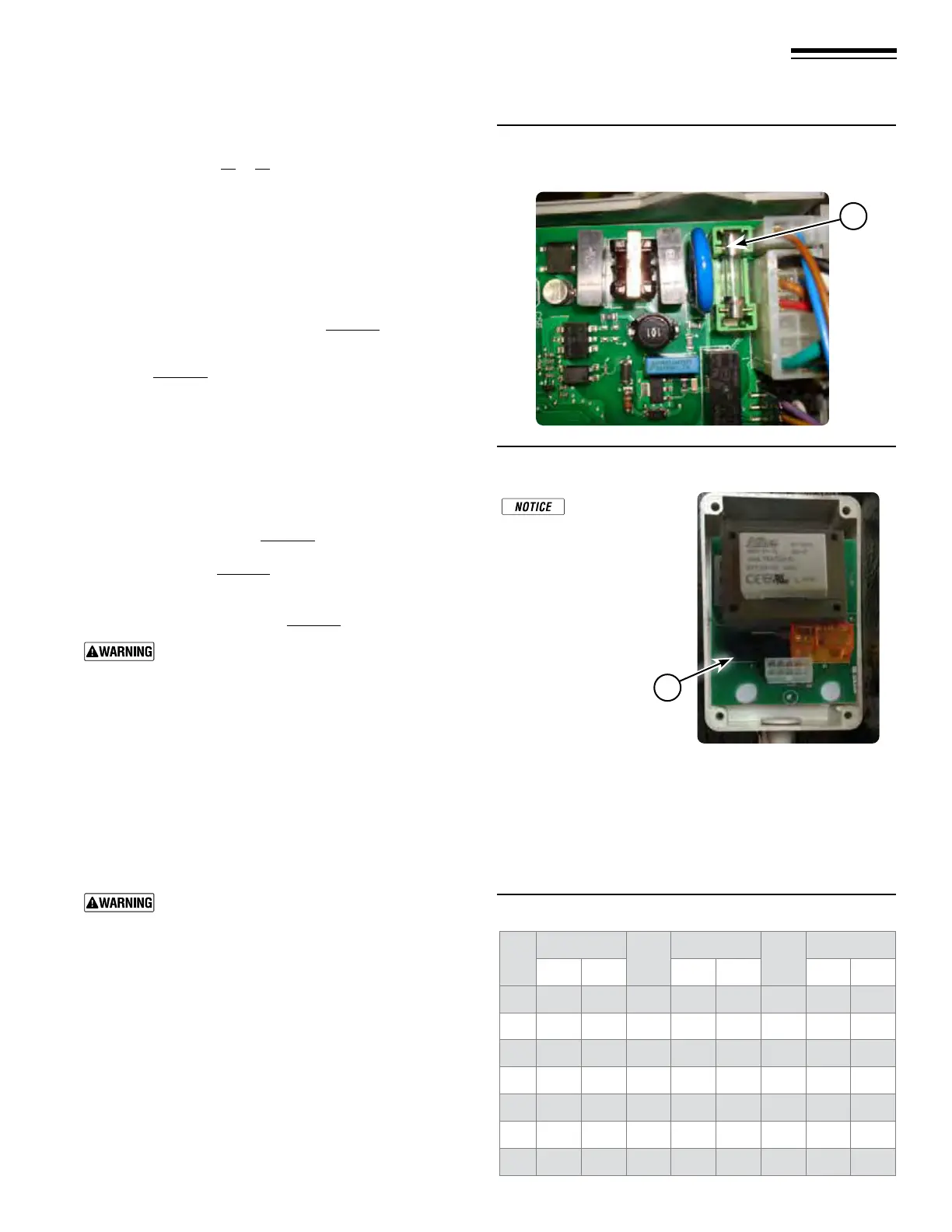
Check control fuse
See Replacement parts for fuses, page123.
ALWAYS check circuit fuses before replacing
control or any major components (blower, etc.).
If a fuse is blown, it can prevent the control or
other components from operating.
1. Turn OFF power to boiler at external line switch. en
remove the jacket door.
2. Locate fuses using Figure115 and Figure116.
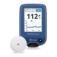
3. Remove and inspect the fuses (Itema, Figure115 or Item
b, Figure116).
4. If necessary, replace the fuses:
a. Control circuit fuse is a 250 VAC 3.15-amp rated fuse.
(Part number 640-000-122)
b. ermostat-relay circuit fuse is a 250 Volt 630mA rated
fuse. (Part number 640-000-123)
Do not jumper fuses or replace with any fuse
except as specied. Failure to comply could result
in severe personal injury, death or substantial
property damage.
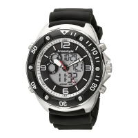
Checking temperature sensors
1. e boiler temperature sensors (ue, outdoor, return water
and supply water) are all resistance-type devices. Figure117
shows the correct value for the sensor at various tempera-
tures. For dual sensors, the temperature dierence between
the sensors must be no more than 10°F. (Supply outlet 200
sensor).
2. Use the resistance values at 32°F, 60°F, 70°F and 212°F to
measure the sensor resistance at known temperatures (ice
point, room temperature and sea level boiling point). For
ice point and boiling point, insert the sensor in water at that
temperature. Use an ohmmeter to read resistance value.
3. To check whether the
FreeStyle
® control is correctly sensing
temperature, you can use a resistance decade box. Connect
the decade box temporarily in place of a sensor and read the
corresponding temperature on the
FreeStyle
® control display.
e temperature should be close to the value corresponding
to the input resistance.
Figure 115 Control circuit fuse location
Figure 116 Thermostat-relay circuit fuse location
Figure 117 Sensor resistance values
Installer/homeowner
note, in case of an
“open circuit” of the
ermostat-relay fuse the
boiler can run in DHW
mode but NOT in Central
Heating mode.
Fuse located on rear of circuit board
a
b