2008T Troubleshooting Guide
P/N 490292 Rev. A
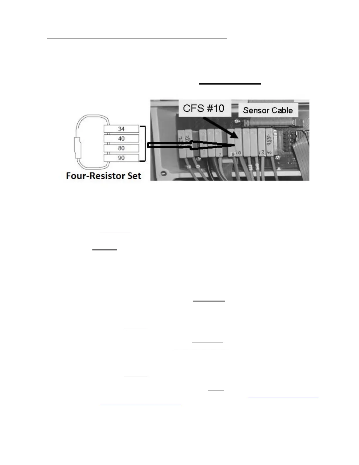
F- 9.0.5 GOOD FLOW PUMP PRESSURE / ISOLATE CFS CIRCUIT
a) Return to Dialysis Program (“Select Program”→ ‘Dialysis’ → ‘Enter’)!
b) From the Home screen, set [Dialysate Flow] to
500 ml/min and press ‘Enter’
c) Figure below, insert one of the resistor plugs, from the FOUR-RESISTOR SET, into CFS #10’s
distribution board position, “x10, CFS”.
d) Call debug screen 10. Does ACFS go to 0.0?
Yes ACFS = 0.0! See procedure number F- 9.0.6 (page 110).
No ACFS DOES NOT = 0.0! See parts a AND b below:
a) ENSURE the resistor plug was placed correctly at position “CFS” before continuing! If
not, repeat procedure number F- 9.0.5 (page 109) from part c.
b) Leaving the resistor plug installed for now, FOUR (4) possible bad components:
1) Actuator-Test Board
1
OR; 2) Sensor Board
2
OR 3) Sensor Board cable
3
OR;
4) Distribution board.
1
A) With the machine off, swap in a known good Actuator-Test Board
a
; B) Return to
Dialysis Program (“Select Program” → Dialysis’ → ‘Enter’); C) If ACFS = 0.0 the
previous Actuator-Test Board is bad.
a
To LOCATE the board refer to Figure 4A (page 10)
2
A)
With the machine off, swap in a known good Sensor Board
b
; B) Place the machine
into T and C Mode (refer to OPERATING MODES (page 19); C) IMPORTANT! Return
to Dialysis Program (“Select Program” → Dialysis’ → ‘Enter’). If ACFS = 0.0 the
previous Sensor Board is bad.
b
To LOCATE the board refer to Figure 4A (page 10)
3
The Sensor Board cable can be checked. NOTE three (3) CFS TRANSDUCER
connections will be checked and proceed to page 569, SECTION 17 - CHECKING
THE SENSOR BOARD CABLE.

 Loading...


