2008T Troubleshooting Guide
P/N 490292 Rev. A
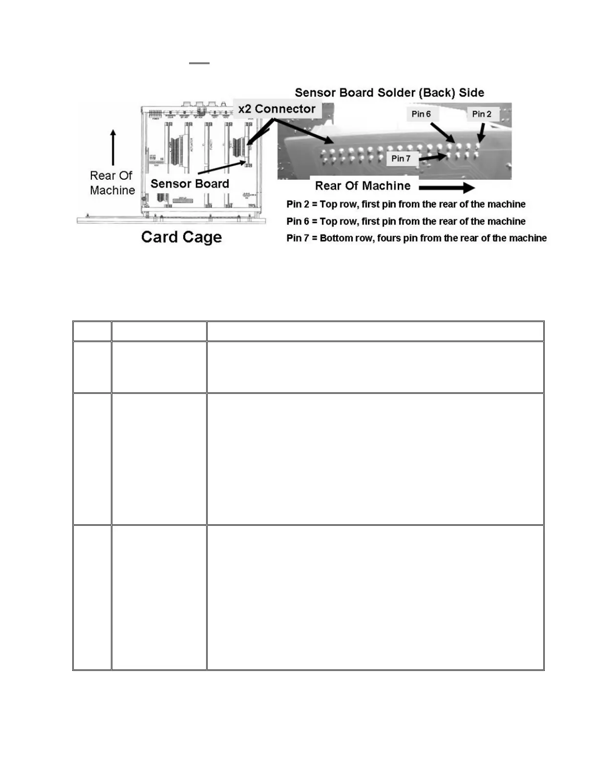
E) Per the Figure below AND as directed in Table 11 below, measure from the solder (back) side of the
Sensor Board’s X2 connector starting at pin #2:
Figure 90 – Electronic Card Cage (Sensor Board)
Table 11 – Sensor Board ‘X2’ DC Voltage Checks (Refer also to Figure 90)
X2 Pin
X2 Pin Location Your Response:
2 Top row, first pin
from the REAR of
the machine
• IF less than 0.5 volts DC: Measure at pin 6 (next row in table)
• IF more than 0.5 volts DC: Bad Actuator-Test Board (see page 10).
6 Top row, third pin
from the REAR of the
machine
• IF less than 4.5 volts DC: See procedure number BL- 6.0.0 (page 565).
• IF more than 5.2 volts DC: See procedure number BL- 6.0.0 (page 565).
• IF between 4.5 and 5.2 volts DC: From debug screen 4, does LEAK = the pin
6 measurement within +/- 0.3 volts DC?
Yes LEAK = pin 6 (+/- 0.3). Measure at pin 7 (next row in table).
No LEAK NOT within +/- 0.3 of pin 6 = Bad Sensor Board (see page 10).
7 Bottom row, fourth
pin from the REAR of
the machine
• IF less than 4.0 volts DC: See procedure number BL- 6.0.0 (page 565).
• IF more than 6.0 volts DC: See procedure number BL- 6.0.0 (page 565).
• IF between 4.0 and 6.0 volts DC: From debug screen 4, does DIMN = the pin
7 measurement within +/- 0.3 volts DC?
Yes DIMN = pin 7 (+/- 0.3). See procedure number BL- 6.0.0 (page 565).
No DIMN does NOT within +/- 0.3 of pin 7= Bad Sensor Board (see page 10).

 Loading...


