S90-010 M FRICK
QUANTUM™ COMPRESSOR CONTROL PANEL
Page 32 MAINTENANCE
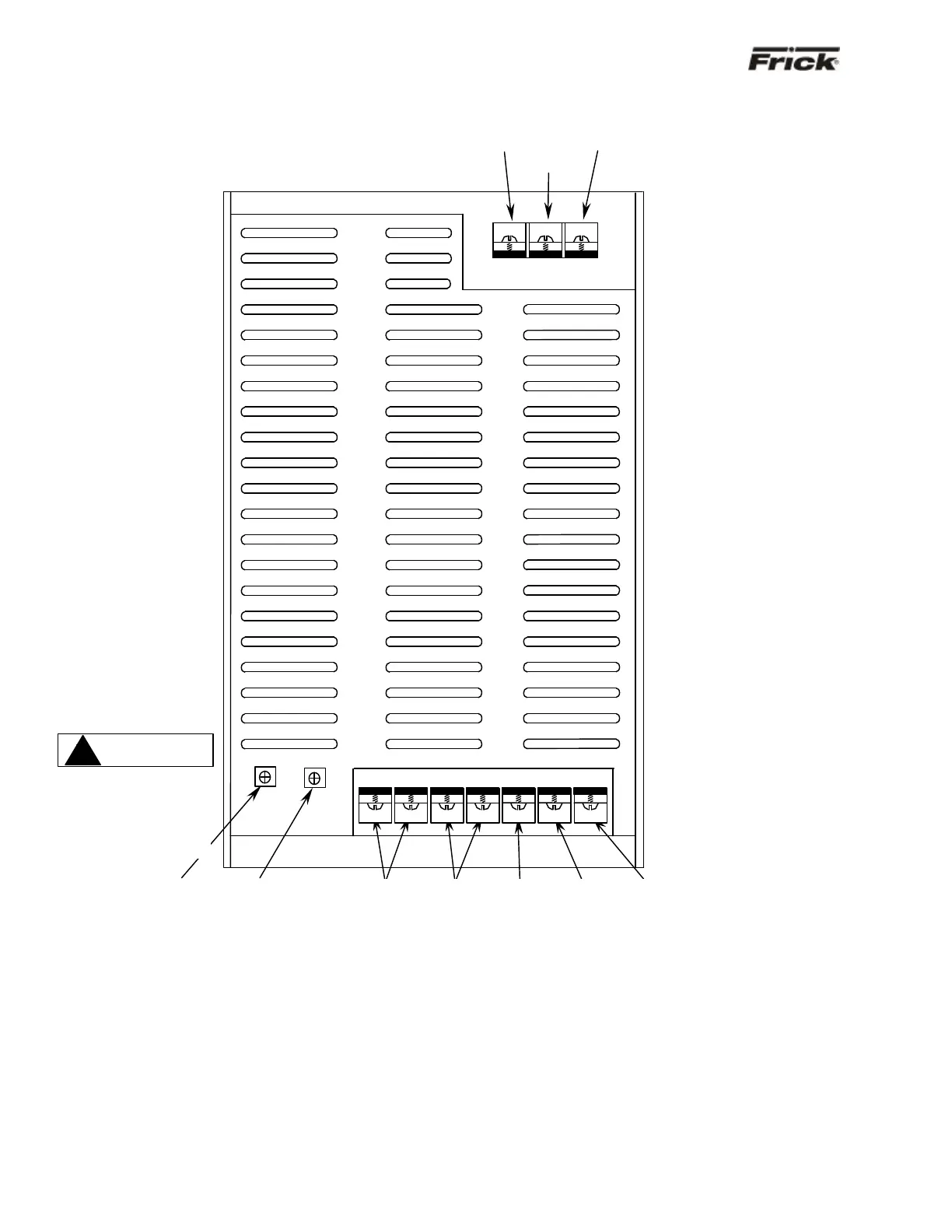
QUANTUM™ PANEL D.C. POWER SUPPLY LAYOUT (POWER-ONE)
INPUT: TB1 INPUT: TB2
SCREW TERMINAL CONNECTIONS: SCREW TERMINAL CONNECTIONS
Pin 1 AC GROUND PIN 1 OUTPUT V4 (+12V)
Pin 3 AC NEUTRAL PIN 2 OUTPUT V3 (-12V)
PIN 5 AC LINE PIN 3 OUTPUT V2 (+12V)
PIN 4 COMMON (GND)
PIN 5 COMMON (GND)
PIN 6 OUTPUT V1 (+5V)
PIN 7 OUTPUT V1 (+5V)
Note: The Power One power supply utilizes screw connections for both the AC and the DC connections. The Condor supply,
on the next page, utilizes connectors. Additionally, both the +5 Vdc and the +12 Vdc can be adjusted on the Power One
supply, whereas the Condor supply can only be adjusted for +5 Vdc.
V2
V1
V4
V3
V2
GND
V1
Use only a screwdriver
with an insulated shaft
to perform adjustment
(see NS-10-02 for
details).