RWB II PLUS ROTARY SCREW COMPRESSOR UNITS
FORMS
S70-200 IOM
Page 53
Adjustable Safety Setpoints
High Discharge Pressure Stop Load _____ Force Unload _____ Alarm ______ Delay ______ Shutdown _____ Delay _____
High Discharge Temp. Stop Load _____ Force Unload _____ Alarm ______ Delay ______ Shutdown _____ Delay _____
Motor Amps ______ Volts ______ Service Factor _______ Horsepower _______ CT Factor ______ Recycle Delay _______
Low Motor Amps Shutdown ______ Delay ______ Force Unload Inhibit Delay _______
High Motor Amps Stop Load _____ Force Unload _____ Alarm ______ Delay ______ Shutdown _____ Delay _____
High Oil Temperature Alarm _______ Delay ______ Shutdown ______ Delay ______
Low Oil Temperature Alarm _______ Delay ______ Shutdown ______ Delay ______ High Level Shutdown Delay _____
Low Separator Oil Temp. Alarm _______ Delay ______ Shutdown ______ Delay ______
Drive Train Alignment
Ambient Temperature at Time of Alignment _______ Oil Separator Temperature at Time of Alignment ________
Motor Coupling Type ___________ Size ___________ Distance Between Coupling Hub Faces __________
Soft Foot Check
OK as Found Shimming Required Amount of Shims used to Correct __________
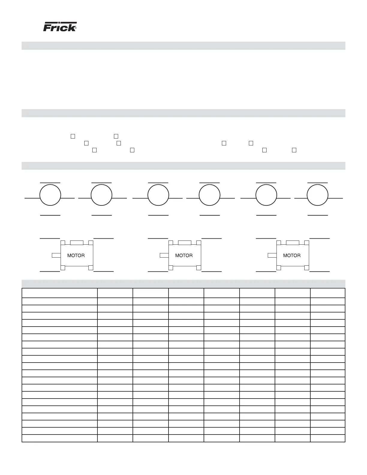
Indicator Readings in
in./1000 mm Indicator Clamped to Motor Compressor
Indicator Readings Facing
Compressor Motor Magnetic Center Checked Marked N/A
Compressor Coupling Hub Runout ___________ Motor Coupling Hub Runout ____________
Initial Cold Alignment Initial Hot Alignment Final Hot Alignment
Operating Log Sheet
Date
Time
Hour Meter Reading
Equip. Room Temp.
Suction Pressure
Suction Temperature
Suction Superheat
Discharge Pressure
Discharge Temperature
Corresponding Temperature
Oil Pressure
Oil Temperature
Oil Filter Pressure Drop
Separator Temperature
Slide Valve Position
Volume Ratio (VI)
Motor Amps / FLA %
Capacity Control Setpoint
Oil Level
Oil Added
Seal Leakage (Drops/Min.)
Face Rim
Thickness of Shims Added
Face Rim
Thickness of Shims Added
Face Rim
Thickness of Shims Added