RWB II ROTARY SCREW COMPRESSOR UNITS
INSTALLATION
S70-200 IOM
Page 6
225 5 127.0 1/32 .914 .004 .102 .004 .102 7.5 10.5
1
/
4
-20 UNRF
262 5 127.0 1/32 .914 .004 .102 .004 .102 22 30.6
3
/
8
-24 UNRF
312 5-1/2 139.7 3/64 1.295 .004 .102 .004 .102 37 51.5
7
/
16
-20 UNRF
350 6 152.4 3/64 1.295 .004 .102 .004 .102 55 76.5
1
/
2
-20 UNRF
375 7 177.8 1/16 1.574 .004 .102 .004 .102 55 76.5
1
/
2
-20 UNRF
425 7 177.8 1/16 1.574 .004 .102 .004 .102 96 133.6
5
/
8
-18 UNRF
450 8 203.2 1/16 1.574 .004 .102 .004 .102 96 133.6
5
/
8
-18 UNRF
500 9 228.6 5/64 2.083 .004 .102 .004 .102 250 348.0
7
/
8
-14 UNRF
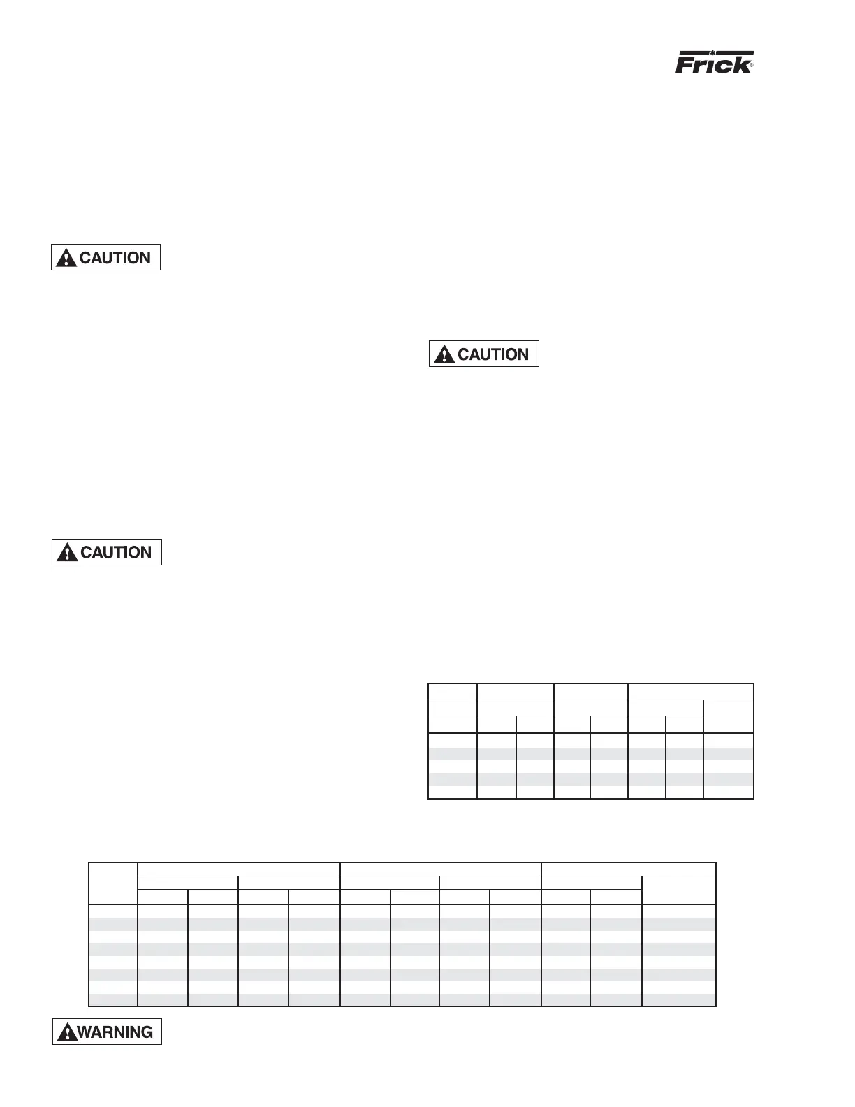
BP HUB FACE * DISC PACK CLAMP BOLT
SERIES SPACING BOLT TORQ. TORQ. DRY SIZE
SIZE in. mm ft-lb Nm ft-lb Nm UNF
BP48 4.88 124 40 54 41 56
3
/
8
-24
BP53 5.88 150 60 81 65 88
7
/
16
-20
BP58 6.00 152 120 163 100 136
1
/
2
-20
BP58 6.69 170 120 163 100 136
1
/
2
-20
BP63 7.00 179 120 163 100 136
1
/
2
-20
* Max total indicator reading .003 in. or .076 mm for all siz es.
All rotating power transmission equipment is potentially dangerous. Ensure that the couplings are
properly guarded prior to turning on the pow er. Cou pling guards are provided with the equipment
and must be in place and se cured properly while the equipment is in operation.
SERIES 52 COUPLING DATA TABLE
3. Adjust the distance between hub faces as specifi ed in the
DBZ-B Data Table by sliding the hubs. Key and secure hubs
to the shafts by tightening setscrews.
4. Reinstall the eight previously removed bolts and lock nuts.
Alternately tighten each locknut as you would the lug nuts on
an automobile. NOTE: ALWAYS TURN THE NUT. NEV ER
TURN THE BOLT.
5. Torque the locknuts to the value shown in the DBZ-B Data
Table for the size coupling being in stalled.
Lubricated and/or plated bolts and
locknuts develop high er bolt ten-
sion with less tight en ing than those
that are dry and not plated. Torques for lu bri cat ed and/or
plated bolts and lock nuts will gen er al ly fall in the low er range;
while those that are dry or as received from the fac to ry fall
into the up per range. Torque read ings should be ob served
while lock nut is being turned.
6. Pro ceed to cou pling align ment.
SERIES 52 COUPLING – The Th o mas Series 52 coupling is
also used on applications above 600 HP. It has two drive hubs,
a cen ter spool, and disc packs which are bolted be tween the
cen ter spool and each drive hub. A cen ter spool and two fl ex-
i ble steel disc packs serve as the drive el e ment. These three
parts, sit u at ed be tween the mo tor and com pres sor hubs,
pre vent ax i al end fl oat be tween the mo tor and com pres sor
shafts. End fl oat tends to occur with sleeve bear ing motors.
The mag net ic center of the sleeve bearing mo tors must be
de ter mined and main tained by se cur ing the cou pling hub to
the motor shaft with the shaft properly lo cat ed.
Injury may occur if loose cloth ing,
etc. be comes en tan gled on the
spin ning mo tor shaft.
If the motor is cou pled to the com pres sor us ing a fi xed-end-
play cou pling such as the Series 52 cou pling and the motor
is not prop er ly cen tered, the ad di tion al thrust loads will be
trans mit ted to the com pres sor bear ings. This ad di tion al thrust
could re sult in pre ma ture bear ing fail ure. Install as follows:
1. Before proceeding with the alignment process found
on pages 7 and 8 of this manual, disassemble the Series
52 coupling noting the arrangement of bolts, washers,
and nuts as THEY MUST BE REPLACED IN THE SAME
OR DER. Mark the adjoining bolt holes of each part, the two
hubs, the two disc packs, and the center spool, so they are
put back together in the same position.
2. Mount the coupling hubs on their respective shafts. The
hub is bored for an interference fi t on the shaft. Heating of
the coupling hub may be necessary for assembly. DO NOT
SPOT HEAT THE HUB as it may cause distortion. Heat in
water, oil, or use a SOFT open fl ame and quickly position
on the shaft.
3. Adjust the distance between hub faces, as specifi ed in the
Series 52 Coupling Data Table, by sliding the hubs. Key and
secure the hubs to the shafts by tight en ing the set screws.
4. Reassemble the coupling with the disc packs and the
cen ter spool. Ensure that they are reassembled exactly as
they were disassembled.
WOODS BP SERIES COUPLING – is also used on ap pli -
ca tions above 600 HP. It utilizes a cen ter spool and two fl ex-
i ble steel disc packs as the drive el e ment. These three parts,
sit u at ed be tween the mo tor and com pres sor hubs, prevent
axial end fl oat be tween the mo tor and com pres sor shafts.
End fl oat tends to occur with sleeve bearing motors.
Injury may oc cur if loose cloth ing,
etc. be comes en tan gled on the
spin ning motor shaft.
If the motor is cou pled to the com pres sor us ing a fi xed-end-
play cou pling and the motor is not prop er ly cen tered, the
ad di tion al thrust loads will be trans mit ted to the com pres sor
bearings. This ad di tion al thrust could re sult in pre ma ture
bearing fail ure. Install the BP Series coupling using the fol-
low ing in struc tions:
1. Before proceeding with the alignment process in the fol-
low ing section, dis as sem ble the BP Series coupling not ing
the ar range ment of bolts, washers, and nuts as THEY
MUST BE RE PLACED IN THE SAME OR DER. Mark the
adjoining bolt holes of each part, the two hubs, the two disc
packs, and the center spool, so they are put back together
in the same position.
2. Install the motor and compressor coupling hubs on their
respective shafts with the keys. Ensure that the hubs slide,
so that when the shim packs are installed, no axial stresses
are transferred to the shim packs because the coupling hub
is stuck.
BP SERIES COUPLING DATA TABLE
COUP- HUB FACE MAX TOTAL INDICATOR READ ING CLAMP BOLT
LING SPACING +/- ANGULAR PARALLEL TORQUE (LUBE)
SIZE
SIZE in. mm in. mm in. mm in. mm ft-lb Nm