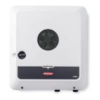
Ite
m
Description
(1) Switchable multifunction current interface.
For more details, refer to the section below entitled "Explanation of the
multifunction current interface"
Use the 2-pin mating connector supplied with the inverter to connect to
the multifunction current interface.
(2)
(3)
IN Fronius Solar Net connection / interface protocol IN
OUT Fronius Solar Net connection / interface protocol
"Fronius Solar Net" / interface protocol input and output for connecting
to other DATCOM components (e.g. inverter, Fronius sensor box, etc.)
If several DATCOM components are linked together, a terminating plug
must be connected to every free IN or OUT connection on a DATCOM
component.
For inverters with a Fronius Datamanager plug-in card, two terminating
plugs are supplied with the inverter.
(4) The "Fronius Solar Net" LED
indicates whether the Fronius Solar Net power supply is available
(5) The "Data transfer" LED
flashes while the USB flash drive is being accessed. The USB flash drive
must not be removed while recording is in progress.
(6) USB A socket
for connecting a USB flash drive with maximum dimensions of
65 x 30 mm (2.6 x 2.1 in.)
The USB flash drive can function as a datalogger for any inverter that it
is connected to. The USB flash drive is not included in the scope of sup-
ply of the inverter.
(7) Floating switch contact (relay) with mating connector
Max. 250 V AC / 4 A AC
Max. 30 V DC / 1 A DC
Max. 1.5 mm² (AWG 16) cable cross-section
Pin 1 = NO contact (normally open)
Pin 2 = C (common)
Pin 3 = NC contact (normally closed)
For a more detailed explanation, please see the "Menu items in the
Setup menu / Relay" section.
Use the mating connector supplied with the inverter to connect to the
floating switch contact.
(8) Fronius Datamanager with WLAN antenna
or
cover for option card compartment
(9) Cover for option card compartment
Explanation of
the multifunc-
tion current in-
terface
Various wiring variants can be connected to the multifunction current interface.
However, these cannot be operated simultaneously. For example, if an S0 meter
is connected to the multifunction current interface, it is not possible to connect
a signal contact for the surge protection device (or vice versa).
13
EN

 Loading...


