Pin 1 = measurement input: max. 20 mA, 100 Ohm measurement resistor (load
impedance)
Pin 2 = max. short circuit current 15 mA, max. open circuit voltage 16 V DC or
GND
Wiring diagram variant 1: Signal contact for surge protection device
Depending on the setting in the Basic menu (Signal Input submenu), the DC SPD
option (surge protection device) either outputs a warning or an error on the dis-
play. Further information on the DC SPD option can be found in the Installation
Instructions.
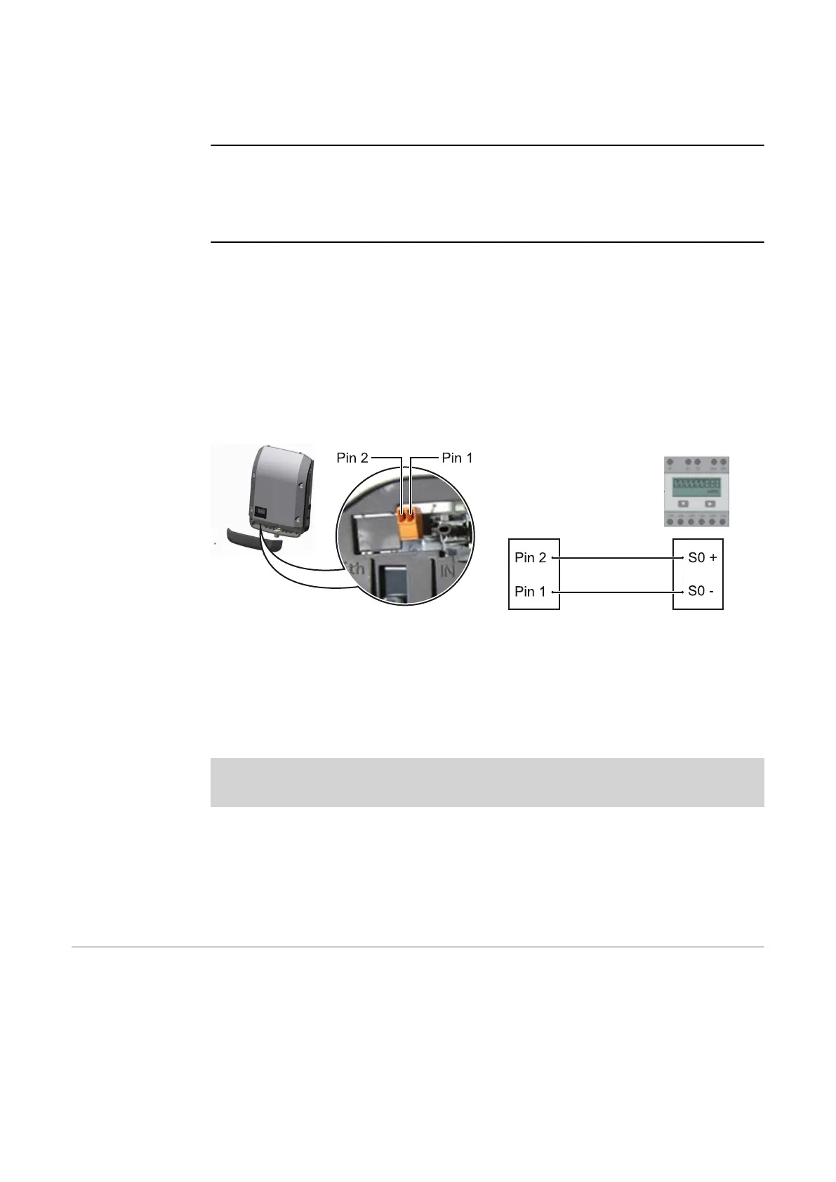
Wiring diagram variant 2: S0 meter
A meter for recording the self-consumption of each S0 can be connected dir-
ectly to the inverter. This S0 meter can be positioned directly at the feed-in point
or in the consumption branch. As one of the settings on the Fronius Dataman-
ager website, a dynamic power reduction can be set under the "DNO Editor"
menu item (see Fronius Datamanager 2.0 Operating Instructions on our website
www.fronius.com)
IMPORTANT! In order to connect an S0 meter to the inverter, it may be neces-
sary to update the inverter firmware.
Requirements for the S0 meter:
-
Must comply with the IEC62053-31 Class B standard
-
Max. voltage 15 V DC
-
Max. current when ON 15 mA
-
Min. current when ON 2 mA
-
Max. current when OFF 0.15 mA
Recommended max. pulse rate of the S0 meter:
PV output kWp [kW] Max. pulse rate per kWp
30 1000
20 2000
10 5000
≤ 5.5 10,000
Description of
the "Fronius Sol-
ar Net" LED
The "Fronius Solar Net" LED is on:
the power supply for data communication within the Fronius Solar Net / inter-
face protocol is OK
The "Fronius Solar Net" LED flashes briefly every 5 seconds:
data communication error in the Fronius Solar Net
14
 Loading...


