40
Installing the compressed air supply
Establishing the
compressed air
supply for the
cleaning device,
function of the
compressed air
relief valve
To establish the compressed air supply:
Depressurise the compressed air supply line of the cleaning device and ensure that it
remains depressurised for the duration of the following work on the device
Screw the supplied compressed air relief valve into the compressed air connection on
the cleaning device
Connect the compressed air supply line to the compressed air relief valve
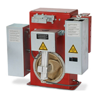
NOTE!
The compressed air supply to the cleaning device can be broken and re-established
by moving the compressed air relief valve forwards and backwards.
The diagram on the left shows the com-
pressed air relief valve in the closed positi-
on = no compressed air supply to the
device
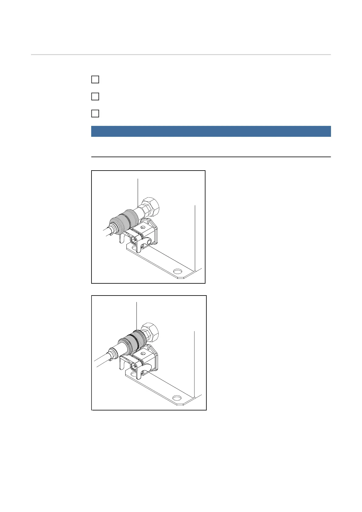
The diagram on the left shows the com-
pressed air relief valve in the open position
= compressed air is being supplied to the
device
1
2
3
 Loading...
