EasyManuals Logo

Fronius Symo 5.0-3-M Service Manual & Spare Parts List

Fronius Symo 5.0-3-M
Go to English
128 pages
To Next Page IconTo Next Page
To Previous Page IconTo Previous Page
Page #86 background imageLoading...
Page #86 background image
86
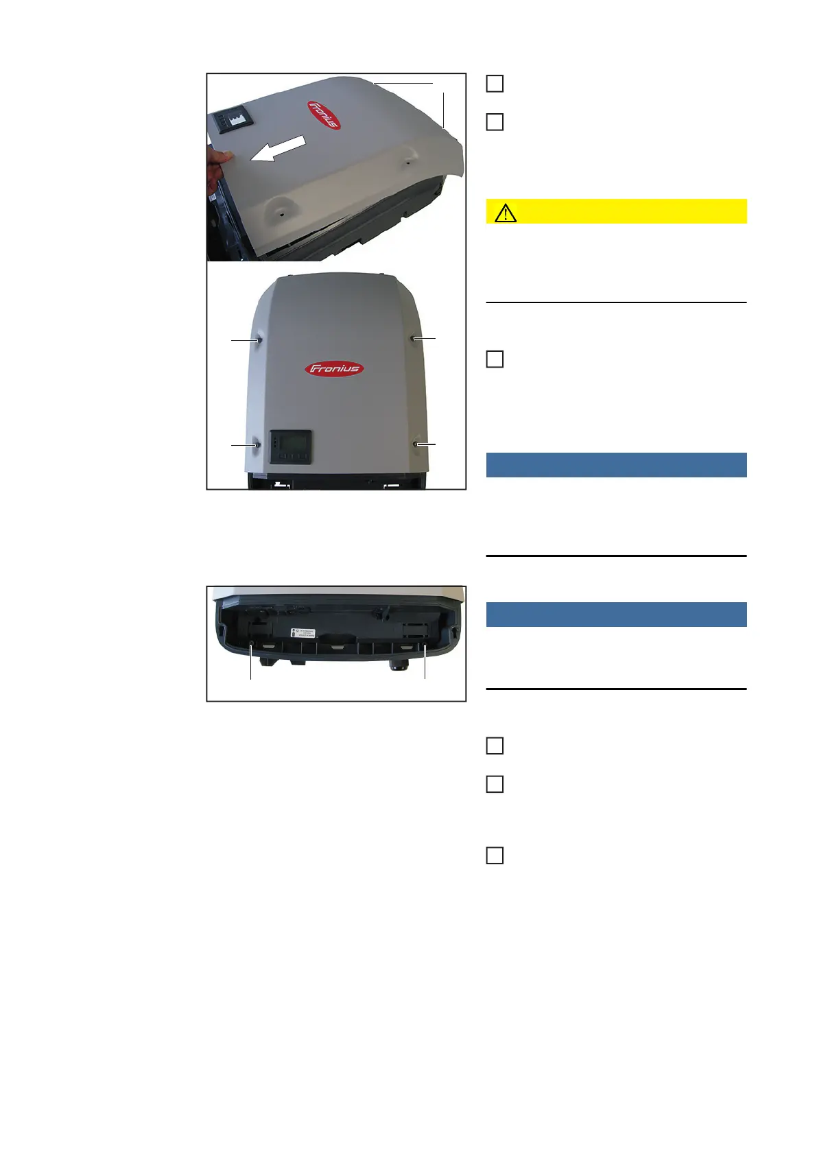
Hang the power stage set cover up on
the fastening pins (5)
While the device is still at an angle, pull
the power stage set cover down and
swivel onto the base frame
CAUTION!
This is the only way to ensure that the
seal foam is correctly positioned and
working properly
Mount power stage set cover using
four 5x18 TX25 screws including gas-
kets (4)
[2.5 Nm]
NOTE!
If the screws no longer grip properly,
replace them with 5x25 TX25 screws
[42,0401,4231]
NOTE!
To avoid damage to the base shell, the
inverter must not exceed an angle of 11°.
Attach the inverter at the top and allow
it to engage with the wall bracket
Using two 5x25 TX25 screws (3), fix to
the wall bracket securely
[2.5 Nm]
If applicable, mount all plug connec-
tions
(5)
(4)
(4)
(4)
(4)
2
3
4
(3) (3)
5
6
7

Table of Contents

Other manuals for Fronius Symo 5.0-3-M

Questions and Answers:

Question and Answer IconNeed help?

Do you have a question about the Fronius Symo 5.0-3-M and is the answer not in the manual?

Fronius Symo 5.0-3-M Specifications

General IconGeneral
AC Nominal Output5.0 kW
Max. Input Voltage1000 V
MPPT Voltage Range200 - 800 V
Number of MPP Trackers2
Dimensions (H x W x D)645 x 431 x 204 mm
Weight19.9 kg
Protection RatingIP 65
Operating Temperature Range-25°C to +60°C
Max. Apparent AC Power5.0 kVA
AC Nominal Voltage3~ 230/400 V
AC Voltage Range184 - 264.5 V
Frequency50 / 60 Hz
THD< 3%
Protection ClassI
Maximum AC Power5000 VA
AC Nominal Frequency50/60 Hz
DC Input Voltage Range200 - 1000 V
Number of DC Connections2
Max. DC Short-circuit Current18.0 A
CoolingActive cooling

Related product manuals