104
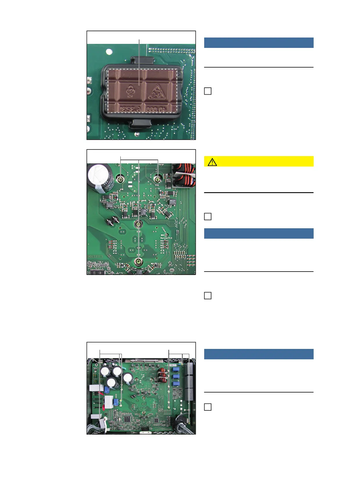
NOTE!
Do not press on the marked area ==>
this will damage the PCM material
Remove two blister packs (10) at the
tabs of the new SymoPS and place on
the faulty SymoPS
CAUTION!
The PCM paste must not be damaged or
removed when inserting the SymoPS
Insert and position the new SymoPS
NOTE!
To avoid applying mechanical stress to
the modules, apply the torque in the
same sequence
Mount the SymoPS modules using four
4x9 TX20 screws (8). Observe the tor-
que sequence to avoid applying me-
chanical stress
First tighten all four screws to [0.5 Nm]
and then tighten them to [2.0 Nm]
NOTE!
The position of the screws (5) varies de-
pending on the power category
4K5 variant:
- fit SymoPS using fourteen 4x9 TX20
screws (5)
[2 Nm]
8k2 variant:
(10)
1
(6)
2
3
(5)(5)
4
 Loading...


