107
EN-US
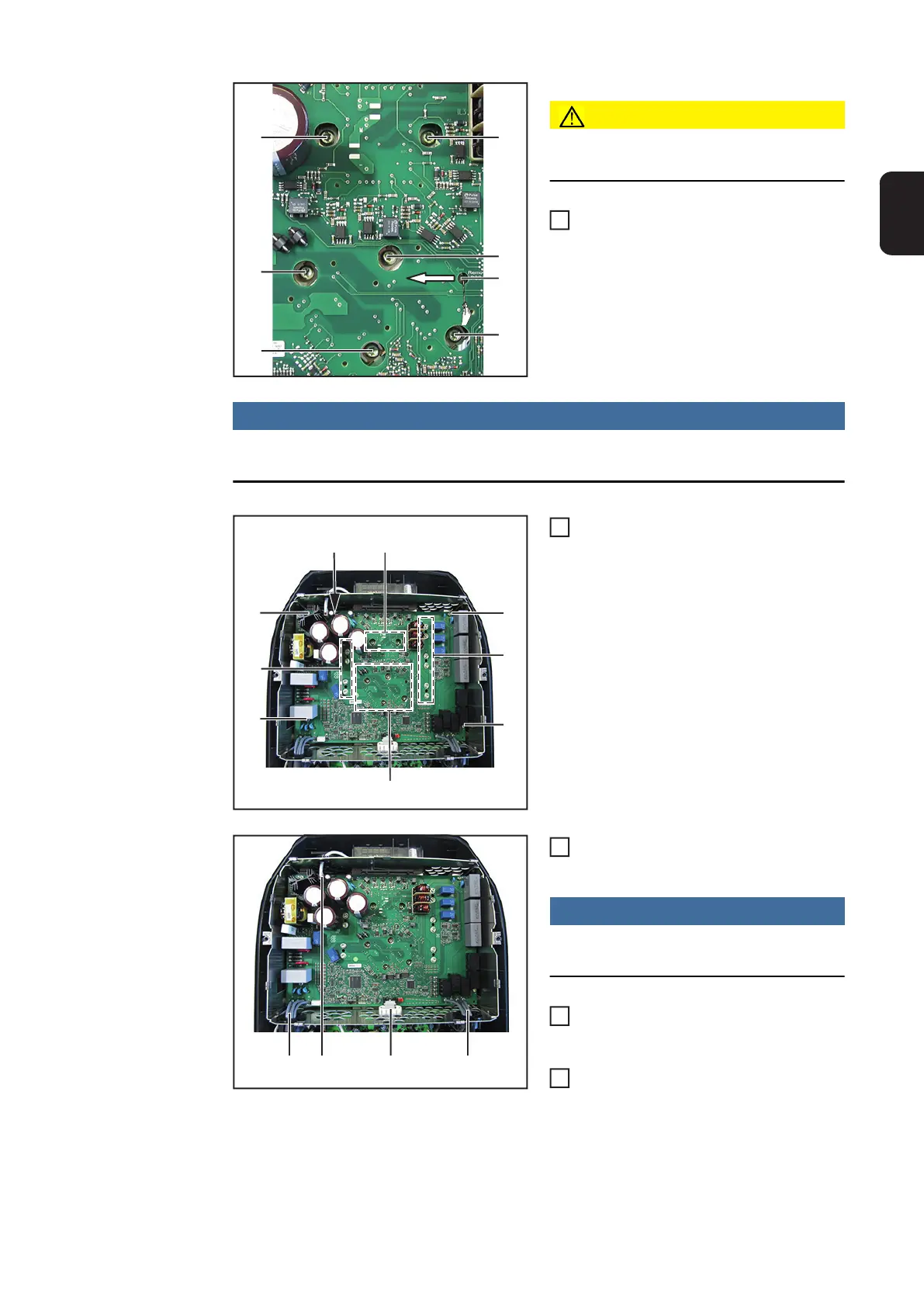
CAUTION!
The PCM paste must not be damaged or
removed when inserting the DuoPS
Insert and position the new DuoPS
Mount the DuoPS modules using six
4x9 TX20 screws (6). Observe the tor-
que sequence to avoid applying me-
chanical stress. First tighten all six
screws to [0.5 Nm] and then tighten
them to [2.0 Nm]
NOTE!
To avoid applying mechanical stress to the modules, apply the torque in the same
sequence
Mount the DuoPS using fifteen 4x9
TX20 screws (5) [2 Nm]
Thread in and connect all cables and
plug connections (1)-(4)
NOTE!
Ensure that the ferrite cores and their
holders are fitted correctly
Close the inverter and place it in the
wall bracket (see "Opening and Clo-
sing the Device")
After switching on the inverter, carry
out a fan test via the display (see Ope-
rating Instructions)
(7)
(6)
(6)
(6)(6)
(6)
(6)
2
(5)
(5)
(5)
(5)
(5)
(5)
(5)
(6)
(6)
3
(1) (3)(2) (4)
4
5
6
 Loading...


