27
EN-US
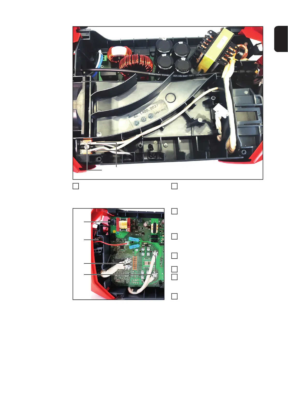
Install the transformer cables (11) in
terminals (10).
Insert terminals and secure with 4x20
TX20 screw (10).
Tightening torque = 2.1 Nm.
Install the transformer cable (13) and
voltage measuring cable with a size 19
mm hexagonal bolt and washer.
Tightening torque = 10 Nm.
Install the transformer cables with 4
M5x12 TX25 screws (14).
Tightening torque = 3.0 Nm.
Install the transformer cables with 4
M5x16 TX25 screws (14).
Connect the remote control cable (12)
Install the HF 190 PC board according
to the chapter "Replacing the PC board
HF 190".
Close the housing as per the "Closing
the housing" chapter.
(10)
(2)
(11)
 Loading...


