ASSEMBLY
63
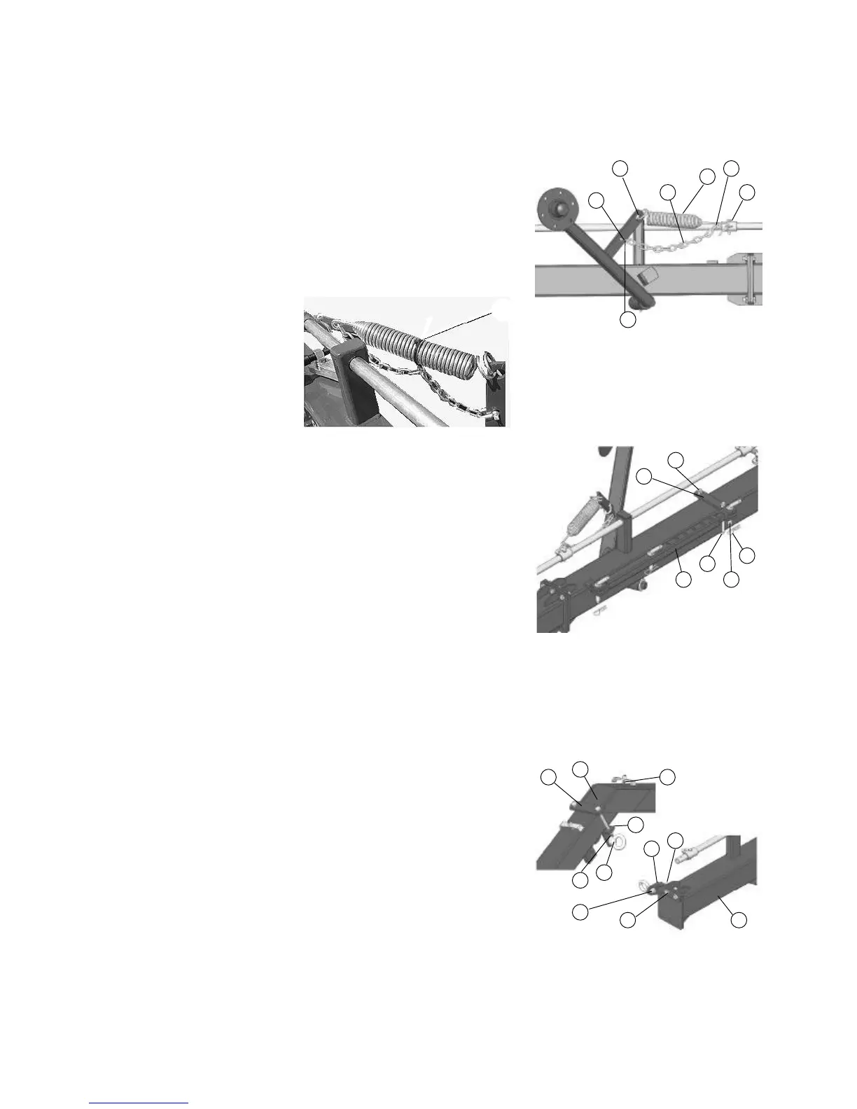
5. Attach spring to wheel arm tab (E). Install one
chainlink (F) over wheel suspension
springhook. Fasten springhook to lifting pipe
tab (D). Connect the last link (G) of the chain
to the wheel arm with clevis link (c) and pin.
A— Spring
B— Chain
C— Clevis link
D— Attachment
E— Arm
F— Chain link
G— Chain link
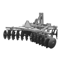
6. Assemble the strap (A) on the rear frame with
a M14x160x120mm U-bolt (E) and nuts (F).
Fasten the assembled bar (B) to the strap and
the frame using L-pins (D) and 4mm diameter
spring pins (C)
A— Blade
B— Bar
C— Spring Pins
D— L-pins
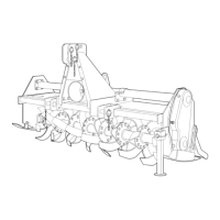
7. Assemble the bracket(A) to frame (F) with
M14x50 cap screw (B) and nuts (G).
Assemble the bracket (C) to the drawbar with
2-holes strap (H), M12x140 cap screws (I)
and nuts (J). Assemble the clevises (D) to the
bracket, but do not tighten the M16 nuts (E)
A— Bracket
B— Screws M14x50
C— Attachment
D— Clevises
E— Nuts M16
F— Frame
G— Nuts M14
H— Strap, 2-hole
I— Screws M12X140
H
There are two tie straps (6) to fix the chain to
the spring in the last two rake wheels only