10-4
10.4 Replacing Temperature Probe
1. Disconnect electrical power to the fryer.
2. Drain the cooking oil from the frypot.
3. Remove cap over elements.
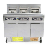
4. Disconnect the wiring harness, which is visible inside the cabinet, containing the red and white
probe wiring. It may be necessary to remove the wire ties.
5. Use a pin pusher (Frymaster Part Number 806-4855) to remove the probe wires from the
connector. Mark each wire for re-assembly. Fig: 10-11
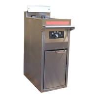
6. Remove the screw(s) securing the probe bracket to the element. Fig: 10-12
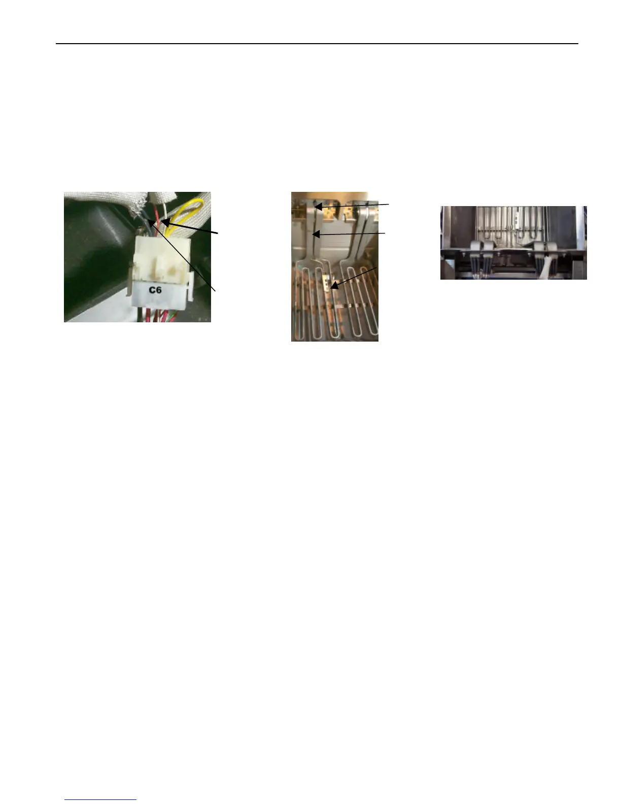
7. Thread the wires through the hole in the tilt plate assembly on the surface ship fryers and through
the access hole near the fixed elements on the sub fryer. Fig: 10-13. Remove the probe and the
securing components from the element.
8. Remove the probe from the probe bracket, and place the new probe into the bracket.
9. Place the new temperature probe assembly onto the element and secure with the screws. Clip the
probe onto the rear of the element. The temperature probe assembly should be oriented in the
same manner as the probe being replaced.
10. Thread the probe wires into the harness connector as removed in Steps 6 & 7.
11. Lower the element into the frypot. (surface ship only).
12. Place the housing cover over the element housing assembly and secure with screws.
Red & white
probe wires
Black high-limit
wires.
hole
Probe clip
Temp
probe and
bracket
Fig: 10-13
Hardware on fixed elements
in sub fryer.
Fig: 10-11