CHAPTER 15 WIRING DIAGRAMS
15-1
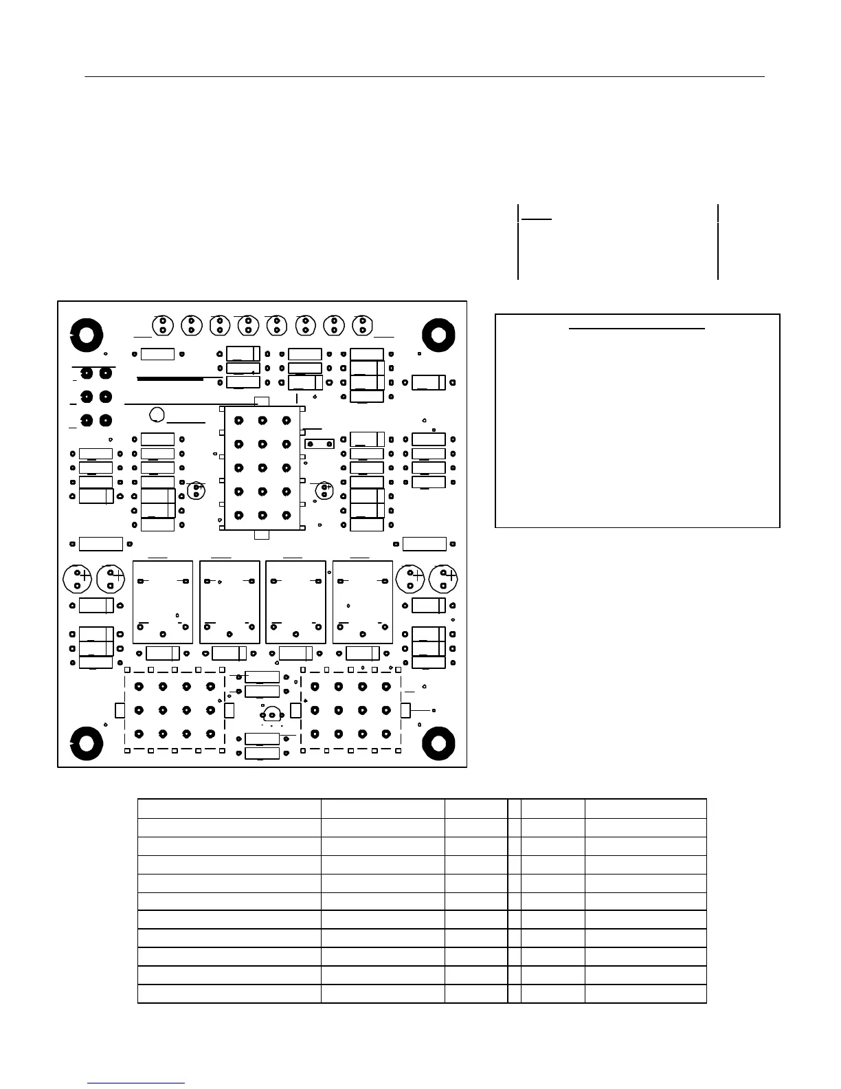
Electric Interface Board
Diagnostic Chart
The following diagram and charts provide ten quick system checks
that can be performed using only a multimeter.
Meter Setting Test Pin Pin Results
12 VAC Power 50 VAC Scale 1 of J2 3 of J2 12-16 VAC
24 VAC Power 50 VAC Scale 2 of J2 Chassis 24-30 VAC
*Probe Resistance (RH) R X 1000 OHMS 11 of J2 12 of J2 See Chart
*Probe Resistance (LH) R X 1000 OHMS 3 of J1 2 of J1 See Chart
Hi-Limit Continuity (RH) R X 1 OHMS 7 of J2 4 of J2 0 - OHMS
Hi-Limit Continuity (LH) R X 1 OHMS 4 of J1 7 of J1 0 - OHMS
Latch Contactor Coil (RH) R X 1 OHMS 8 of J2 Chassis 3-10 OHMS
Latch Contactor Coil (LH) R X 1 OHMS 5 of J1 Chassis 3-10 OHMS
Heat Contactor Coil (RH) R X 1 OHMS 9 of J2 Chassis 18-25 OHMS
Heat Contactor Coil (LH) R X 1 OHMS 6 of J1 Chassis 18-25 OHMS
*Disconnect 15-Pin harness from the computer/controller before testing the probe circuit.
Note: The sealed relays are not
replaceable. If a relay fails the
interface board must be replaced.
Diagnostic LED Legend
CMP indicates power from 12V transformer
24 indicates power from 24V transformer
HI (RH) indicates output (closed) from right Latch
relay
HI (LH) indicates output (closed) from left Latch
relay
HT (RH) indicates output from right Heat relay
HT (LH) indicates output from left Heat relay
AL (RH) indicates output (open) from right Latch
relay
AL (LH) indicates output (open) from left Latch
relay
HIHT CMP HTHI
MADE IN U.S.A.
Frymaster
C
1994
24V
34
5 2
1
1
3
2
SOUND
1
34
5 2
1
34
5 2
1
34
5 2
1
K4
D17
C6
AL AL
D22
1 1
R1
J1
J2
D5
D8
D4D3D2
K3K2K1
R2
Q1
R14
R18
R22
R24
R10
R13
R17
R21
R25
J3
D15
D6
R6
D10
R8
R4
31 2
R3
F1
D16
D1
R5
R7
D9
D7
R16
C5
D14
R12R11
R20
R9
R15
R19
R23
R26 D18
R28 D20
D12
R31R30
D19
D11
R29
D13
D21
R27
C1 C2 C4C3
D29
123
456
789
101112
131415
1
2
3
4
5
6
7
8
9
10
11
12
1
2
3
4
5
6
7
8
9
10
11
12