1.1.4 Replacing the ATO board or Transformer
Disconnect the fryer from the electrical power
supply. Locate the ATO box (see Figure 1 on
page 12), behind the JIB (Jug In Box).
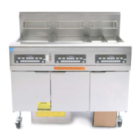
Remove the cover to expose the transformer
and ATO board (see Figure 2). Mark and
unplug any wires or harnesses. Replace the
defective component and reattach all wires or
harnesses. Replace the cover. Once replaced,
reconnect the power. Power cycle all
computers after power has been restored to the
ATO board.
Figure 2
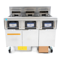
1.1.5 Replacing the ATO Pump or Solenoid
Disconnect the fryer from the electrical power
supply. Locate the ATO pump and solenoid
tree (see Figure 3), behind the ATO box. Mark
and unplug any wires or harnesses. Replace
the defective component and reattach all wires
or harnesses. Once replaced, reconnect the
power.
Figure 3
1.2 MIB (Manual Interface Board) Service Procedures
The MIB (Manual Interface Board) oversees and controls filtration. It receives and sends data
over the CAN (Controller Area Network) to and from various sensors and computers. It
activates the filtration cycle; controlling when actuators should open and close.
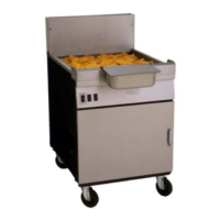
The MIB controller is located inside the left cabinet (see Figure 4). In normal operation a cover
hides the MIB controls and the LED display is visible. The cover is held in place with three torx
screws. In normal operation, an “A” is displayed for automatic mode. The MIB control board is
useful for diagnostic purposes. It allows manual operation of both the actuators and filter pump
without using the M2007 computer.
Figure 4: MIB controller cover.
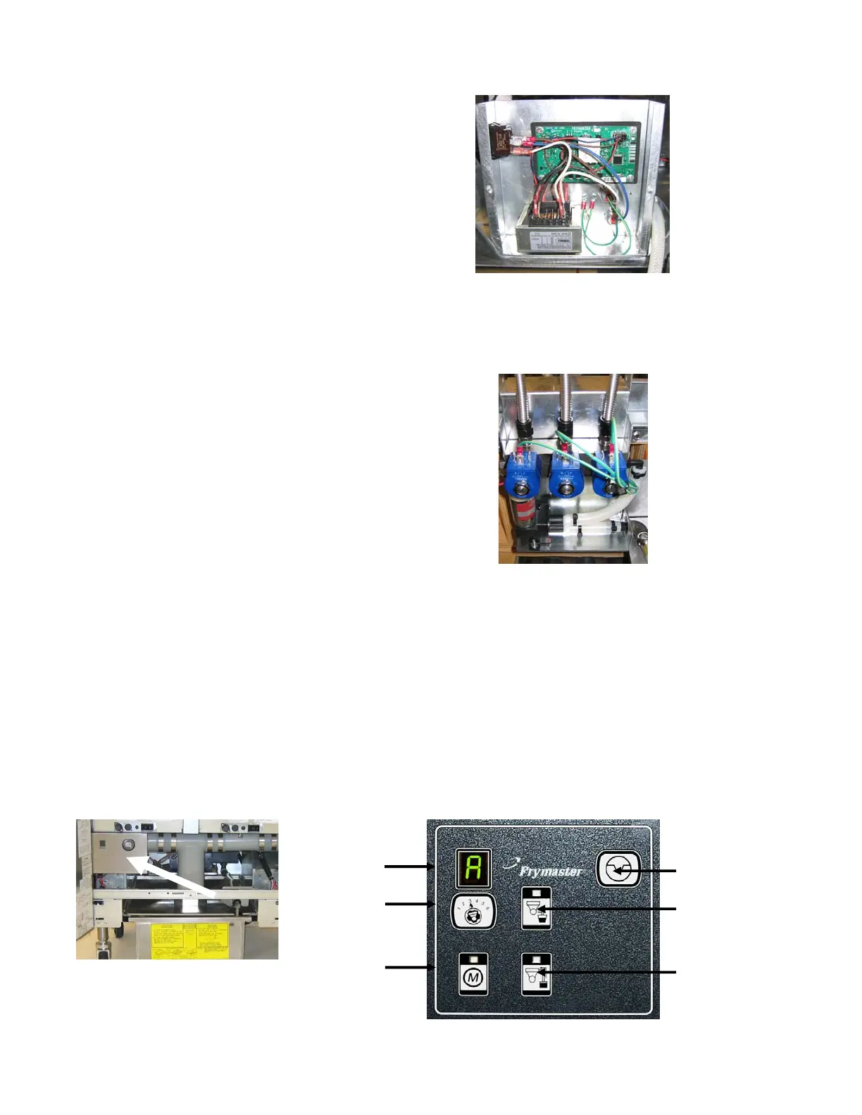
Figure 5
Reset Switch
Drain Switch
Return Switch
Mode Display
Vat Selector
Switch
Manual /Auto
Switch