2-1
Chapter 2 MOUNTING AND WIRING OF THE INVERTER
2.1 Operating Environment
Install the inverter in an environment that satisfies the requirements listed in Table 2.1.
Table 2.1 Environmental Requirements
Item Specifications
Site location Indoors
Ambient
temperature
-10 to +50°C (Note 1)
Relative
humidity
5 to 95% (No condensation)
Atmosphere
The inverter must not be exposed to dust,
direct sunlight, corrosive gases, flammable
gas, oil mist, vapor or water drops.
(Note 2)
The atmosphere can contain only a low level
of salt.
(0.01 mg/cm
2
or less per year)
The inverter must not be subjected to sudden
changes in temperature that will cause
condensation to form.
Altitude 1,000 m max. (Note 3)
Atmospheric
pressure
86 to 106 kPa
3 mm (Max. amplitude) 2 to less than 9 Hz
9.8 m/s
2
9 to less than 20 Hz
2 m/s
2
20 to less than 55 Hz
Vibration
1 m/s
2
55 to less than 200 Hz
2.2 Installing the Inverter
(1) Mounting base
The temperature of the heat sink will rise up to
approx. 90°C during operation of the inverter, so
the inverter should be mounted on a base made
of material that can withstand temperatures of this
level.
Install the inverter on a base made of metal or
other non-flammable material.
A fire may result with other material.
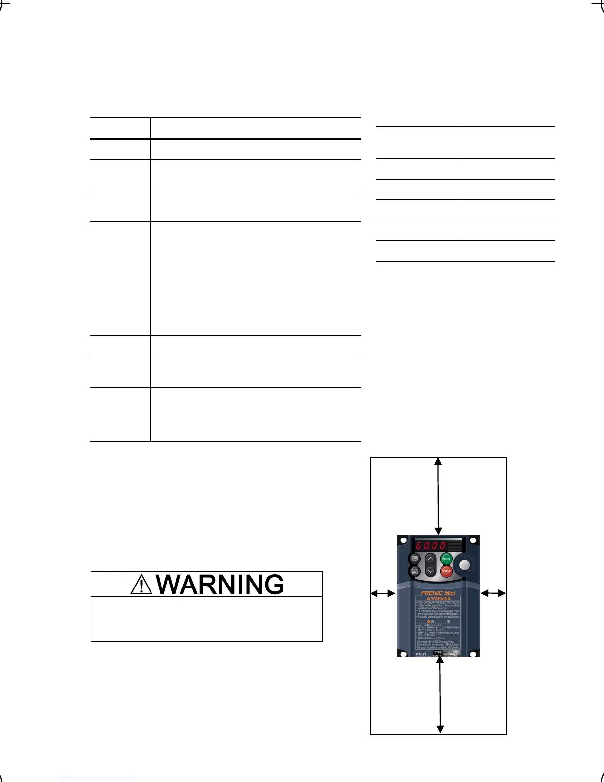
(2) Clearances
Ensure that the minimum clearances indicated in
Figure 2.1 are maintained at all times. When
installing the inverter in the panel of your system,
take extra care with ventilation inside the panel as
the temperature around the inverter tends to
increase.
Table 2.2 Output Current Derating Factor in
Relation to Altitude
Altitude
Output current
derating factor
1000 m or lower 1.00
1000 to 1500 m 0.97
1500 to 2000 m 0.95
2000 to 2500 m 0.91
2500 to 3000 m 0.88
(Note 1) When inverters are mounted
side-by-side without any gap between them
or the NEMA1 kit option is mounted on the
inverter, the ambient temperature should be
within the range from -10 to +40°C.
(Note 2) Do not install the inverter in an
environment where it may be exposed to
cotton waste or moist dust or dirt which will
clog the heat sink in the inverter. If the
inverter is to be used in such an environment,
install it in the panel of your system or othe
dustproof containers.
(Note 3) If you use the inverter in an altitude
above 1000 m, you should apply an outpu
current derating factor as listed in Table 2.2.
Figure 2.1 Mounting Direction and
Required Clearances
Top 100 mm
Bottom 100 mm
Left
10 mm
Right
10 mm

 Loading...


