2-7
2.3.5 Wiring for main circuit terminals and grounding terminals
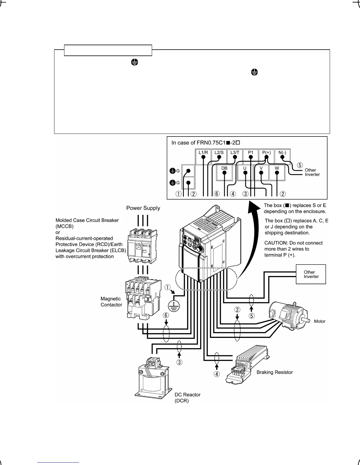
Follow the procedure below. Figure 2.3 illustrates the wiring procedure with peripheral equipment.
c Grounding terminal G*
1
d Inverter output terminals (U, V, and W) and grounding terminal G*
1
e DC reactor connection terminals (P1 and P(+))*
2
f Braking resistor connection terminals (P(+) and DB)*
2
g DC link bus terminals (P(+) and N(-))*
2
h Main circuit power input terminals (L1/R, L2/S and L3/T) or (L1/L and L2/N)
*
1
Use either one of these two grounding terminals on the main circuit terminal block.
*
2
Perform wiring as necessary.
Figure 2.3 Wiring Procedure for Peripheral Equipment
Wiring procedure
(This figure is a virtual representation.)
CAUTION: When wiring the inverter to the power
supply of 500 kVA or more (50 kVA or more for the
single-phase 100 V class series of inverters), be sure to
connect an optional DC reactor (DCR).

 Loading...


