2-4
(2) Arrangement of the control circuit terminals (common to all FRENIC-Mini models)
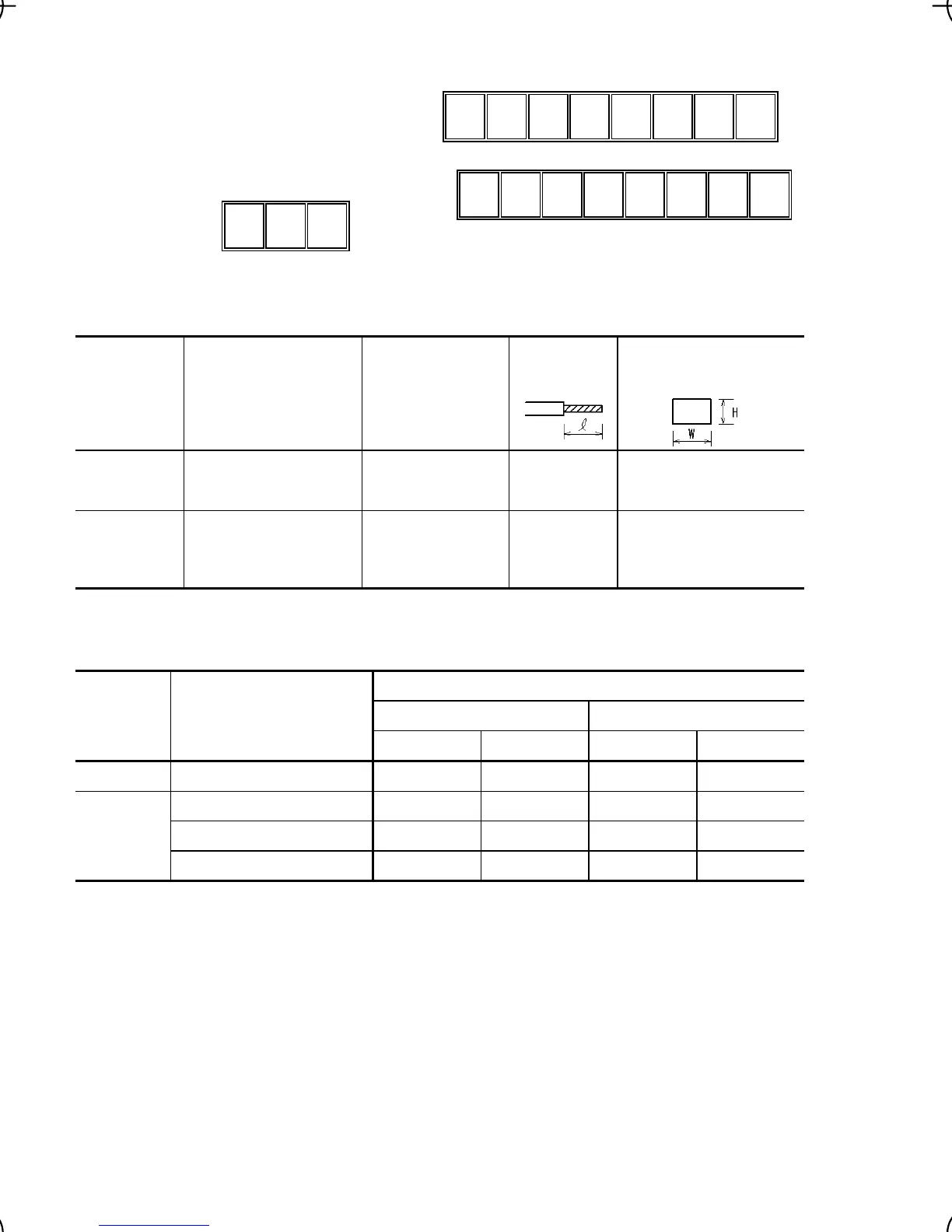
Screw size: M 2 Tightening torque: 0.2 N•m
Screw size: M 2.5 Tightening torque: 0.4 N•m
30A 30B 30C
Y1
11
Y1E FMA C1 PLC
12 13 11 CM
X1 X2 X3
CM FWD REV
Table 2.4 Control Circuit Terminals
Terminal Screwdriver to be used Allowable wire size
Bared wire
length
Dimension of openings in
the control circuit termi-
nals for ferrule*
30A, 30B, 30C
Phillips screwdriver
(JIS standard)
No.1 screw tip
AWG22 to AWG18
(0.34 to 0.75 mm
2
)
6 to 8 mm 2.7 mm (W) x 1.8 mm (H)
Others
Phillips screwdriver for
precision machinery
(JCIS standard)
No.0 screw tip
AWG24 to AWG18
(0.25 to 0.75 mm
2
)
5 to 7 mm 1.7 mm (W) x 1.6 mm (H)
* Manufacturer of ferrules: WAGO Company of Japan, Ltd. Refer to Table 2.5.
Table 2.5 Recommended Ferrule Terminals
Type (216-
)
Screw size Wire size
With insulated collar Without insulated collar
Short type Long type Short type Long type
M2
AWG24 (0.25 mm
2
) 321 301 151 131
AWG22 (0.34 mm
2
) 322 302 152 132
M2 or M2.5
AWG20 (0.50 mm
2
) 221 201 121 101
AWG18 (0.75 mm
2
) 222 202 122 102
The length of bared wires to be inserted into ferrule terminals is 5.0 mm or 8.0 mm for the short or long type,
respectively.
The following crimping tool is recommended: Variocrimp 4 (Part No.: 206-204).
2.3.3 Recommended wire sizes
Table 2.6 lists the recommended wire sizes. The recommended wire sizes for the main circuits for an
ambient temperature of 50°C are indicated for two types of wire: HIV single wire (for 75°C) (before a
slash (/)) and IV single wire (for 60°C) (after a slash (/)),

 Loading...


