2-5
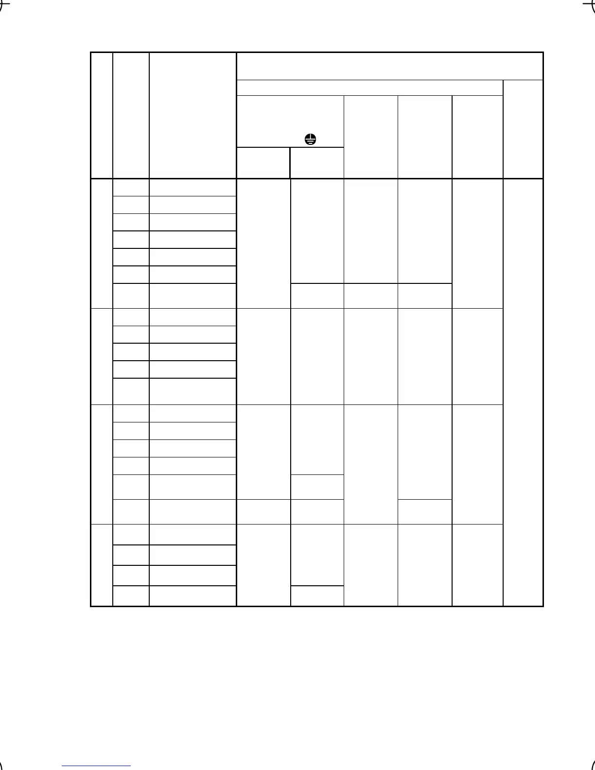
Table 2.6 Recommended Wire Sizes
*1
Recommended wire size (mm
2
)
Main circuit
Main circuit power input
[L1/R, L2/S, L3/T]
[L1/L, L2/N]
Grounding [
G]
Power supply voltage
Nomi-
nal
applied
motor
(kW)
Inverter type
w/ DCR
*2
w/o DCR
Inverter
output
[U, V, W]
DCR
[P1, P (+)]
Braking
resistor
[P (+), DB]
Control
circuit
0.1 FRN0.1C1
-2
0.2 FRN0.2C1
-2
0.4 FRN0.4C1
-2
0.75 FRN0.75C1
-2
1.5 FRN1.5C1
-2**
2.2 FRN2.2C1
-2**
2.0 / 2.0
(2.5)
2.0 / 2.0
(2.5)
2.0 / 2.0
(2.5)
Three-phase 200 V
3.7
FRN3.7C1
-2**
2.0 / 2.0
(2.5)
2.0 / 5.5
(2.5)
2.0 / 3.5
(2.5)
2.0 / 3.5
(2.5)
2.0 / 2.0
(2.5)
0.4 FRN0.4C1
-4
0.75 FRN0.75C1
-4
1.5 FRN1.5C1
-4**
2.2 FRN2.2C1
-4**
Three-phase 400 V
3.7
4.0
FRN3.7C1
-4**
FRN4.0C1
-4**
2.0 / 2.0
(2.5)
2.0 / 2.0
(2.5)
2.0 / 2.0
(2.5)
2.0 / 2.0
(2.5)
2.0 / 2.0
(2.5)
0.1 FRN0.1C1
-7
0.2 FRN0.2C1
-7
0.4 FRN0.4C1
-7
0.75 FRN0.75C1
-7
2.0 / 2.0
(2.5)
1.5 FRN1.5C1
-7
2.0 / 2.0
(2.5)
2.0 / 3.5
(4.0)
2.0 / 2.0
(2.5)
Single-phase 200 V
2.2 FRN2.2C1
-7
2.0 / 3.5
(4.0)
3.5 / 5.5
(6.0)
2.0 / 2.0
(2.5)
2.0 / 3.5
(4.0)
2.0 / 2.0
(2.5)
0.1 FRN0.1C1
-6
0.2 FRN0.2C1
-6
0.4 FRN0.4C1
-6
2.0 / 2.0
Single-phase 100 V
0.75 FRN0.75C1
-6
2.0 / 2.0
2.0 / 3.5
2.0 / 2.0 *3 2.0 / 2.0
0.5
DCR: DC reactor
*1 Use crimp terminals covered with an insulated sheath or insulating tube. Recommended wire sizes are
for HIV/IV (PVC in the EU).
*2 Wire sizes are calculated on the basis of input RMS current under the condition that the power supply
capacity and impedance are 500 kVA (50 kVA for single-phase 100 V class series) and 5%, respectively.
*3 For single-phase 100 V class series of inverters, use the same size of wires as used for the main circuit
power input. Insert the DC reactor (DCR) in either of the primary power input lines. Refer to Chapter 10
for more details.
Note 1) A box (
) in the above table replaces S or E depending on the enclosure.
2) A box (
) in the above table replaces A, C, E, or J depending on the shipping destination.
3) Asterisks (**) in the above table denote the following:
21: Braking resistor built-in type, None: Standard

 Loading...


