2-15
Table 2.8 Symbols, Names and Functions of the Control Circuit Terminals
Classifi-
cation
Symbol Name Functions
[13] Potenti-
ometer
power
supply
Power supply (+10 VDC) for frequency command potentiometer (Potenti-
ometer: 1 to 5 kΩ)
Allowable output current: 10 mA
A potentiometer of 1/2 W rating or more should be connected.
[12] Voltage
input
(1) The frequency is commanded according to the external analog input
voltage.
0 to +10 (VDC)/0 to 100 (%) (Normal mode operation)
+10 to 0 (VDC)/0 to 100 (%) (Inverse mode operation)
(2) Used for reference signal (PID process command) or PID feedback
signal.
(3) Used as additional auxiliary setting for various main frequency com-
mands.
* Input impedance: 22 kΩ
* Allowable maximum input voltage is +15 VDC. If the input voltage is +10
VDC or more, the inverter will limit it at +10 VDC.
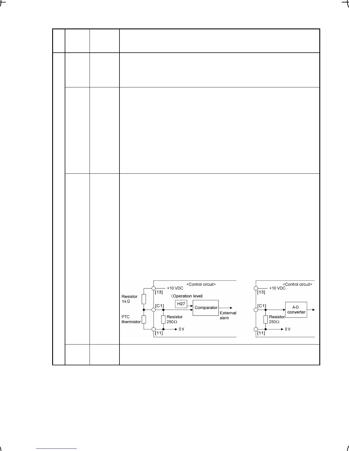
[C1] Current
input
(1) The frequency is commanded according to the external analog input
current.
+4 to +20 (mA DC)/0 to 100 (%) (Normal mode operation)
+20 to +4 (mA DC)/0 to 100 (%) (Inverse mode operation)
(2) Used for reference signal (PID process command) or PID feedback
signal.
(3) Connects PTC (Positive Temperature Coefficient) thermistor for motor
protection.
(4) Used as additional auxiliary setting to various main frequency com-
mands.
* Input impedance: 250 Ω
* Allowable input current is +30 mA DC. If the input current exceeds +20
mA DC, the inverter will limit it at +20 mA DC.
Analog input
[11] Analog
common
Common terminal for analog input and output signals
This terminal is electrically isolated from terminals [CM] and [Y1E].

 Loading...


