2-17
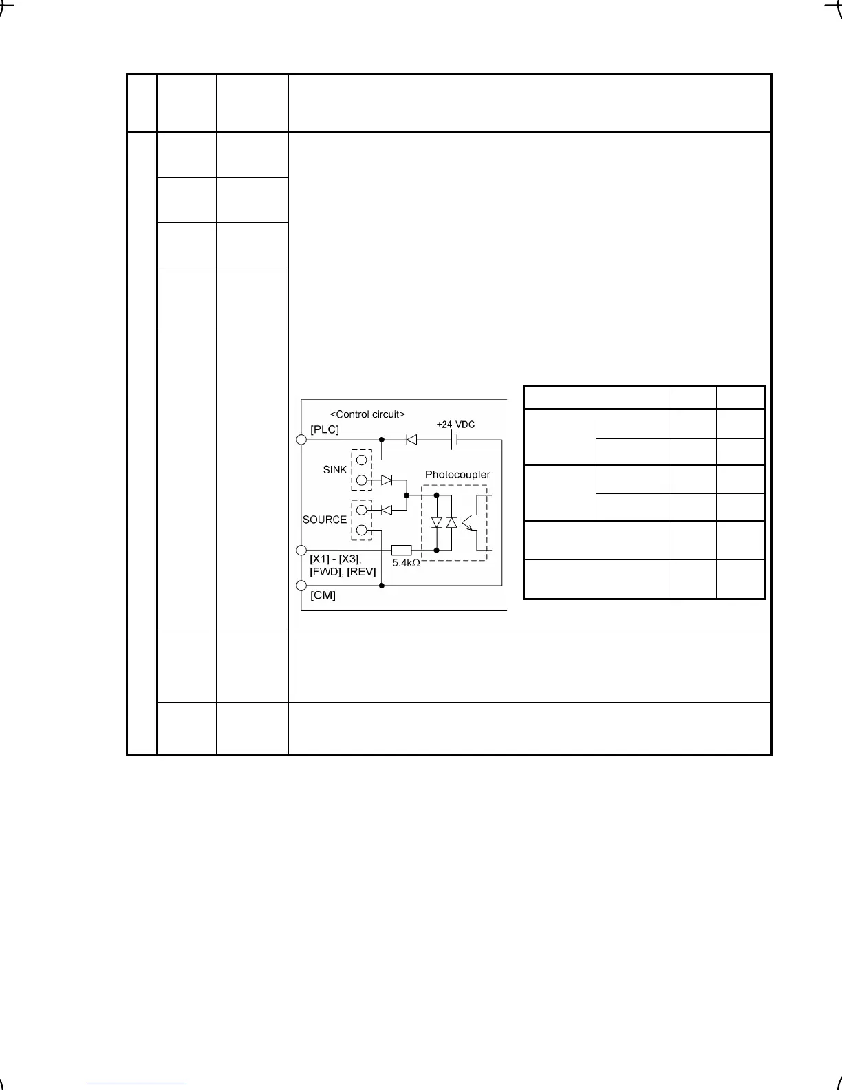
Item Min. Max.
ON level 0 V 2 V
Operation
voltage
(SINK)
OFF level 22 V 27 V
ON level 22 V 27 V
Operation
voltage
(SOURCE)
OFF level 0 V 2 V
Operation current at ON
(Input Voltage at 0 V)
2.5 mA 5 mA
Allowable leakage
current at OFF
- 0.5 mA
Table 2.8 Continued
Classifi-
cation
Symbol Name Functions
[X1] Digital
input 1
[X2] Digital
input 2
[X3] Digital
input 3
[FWD] Forward
operation
command
[REV] Reverse
operation
command
(1) The various signals such as coast-to-stop, alarm from external equip-
ment, and multi-frequency selection can be assigned to terminals [X1] to
[X3], [FWD] and [REV] by setting function codes E01 to E03, E98, and
E99. For details, refer to Chapter 5, Section 5.2 "Overview of Function
Codes."
(2) Input mode, i.e. Sink/Source, is changeable by using the internal jumper
switch.
(3) Switches the logic value (1/0) for ON/OFF of the terminals between [X1]
to [X3], [FWD] or [REV], and [CM]. If the logic value for ON between [X1]
and [CM] is 1 in the normal logic system, for example, OFF is 1 in the
negative logic system and vice versa.
(4) The negative logic signaling cannot be applicable to [FWD] and [REV].
Digital input circuit specifications
[PLC] PLC
signal
power
Connects to PLC output signal power supply.
Rated voltage: +24 VDC (Allowable range: +22 to +27 VDC), Max. 50 mA
This terminal serves also as a transistor output one.
Digital input
[CM] Digital
common
Common terminal for digital input signals
This terminal is electrically isolated from terminals [11] and [Y1E].

 Loading...


