3-25
• If all terminal input signals are OFF (open), segment "g" on all of LEDs 1 to 4 will light
("– – – –").
• Refer to Chapter 5 "FUNCTION CODES" for details.
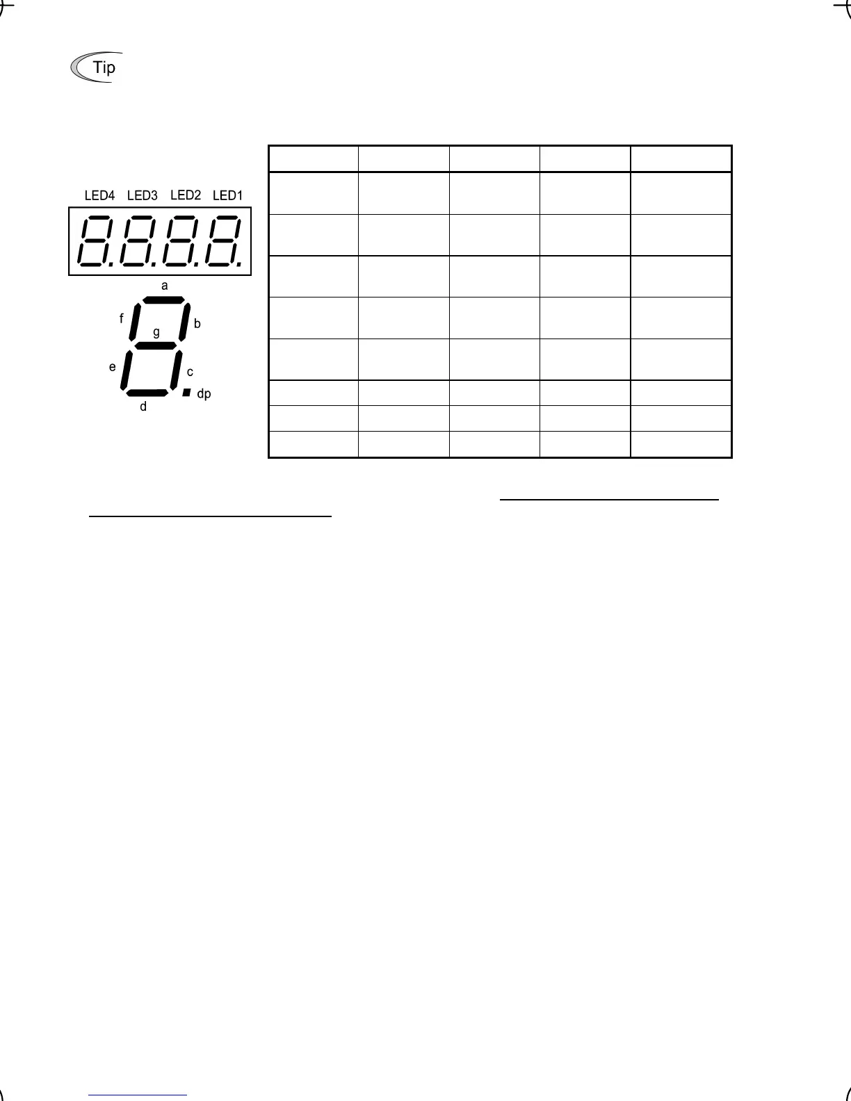
Table 3.16 Segment Display for External Signal Information
Segment LED4 LED3 LED2 LED1
a 30ABC Y1-Y1E —
FWD-CM or
FWD-PLC *
2
b — — —
REV-CM or
REV-PLC *
2
c — — —
X1-CM or
X1-PLC *
2
d — — —
X2-CM or
X2-PLC *
2
e — — —
X3-CM or
X3-PLC *
2
f — — (XF) *
1
—
g — — (XR) *
1
—
dp — — (RST) *
1
—
—: No corresponding control circuit terminal exists.
*1 (XF), (XR), and (RST) are assigned for communication. Refer to "
Displaying control I/O signal ter-
minals under communication control" on the next page.
*2 Terminal [CM] if the jumper switch is set for a sink; terminal [PLC] if the jumper switch is set for a source.
Displaying I/O signal status in hexadecimal format
Each I/O terminal is assigned to bit 15 through bit 0 as shown in Table 3.17. An unassigned bit is
interpreted as "0." Allocated bit data is displayed on the LED monitor in 4 hexadecimal digits ("0" to
"F" each).
With the FRENIC-Mini, digital input terminals [FWD] and [REV] are assigned to bit 0 and bit 1,
respectively. Terminals [X1] through [X3] are assigned to bits 2 through 4. The bit is set to "1" when
the corresponding input terminal is short-circuited with terminal [CM] or terminal [PLC] *, and is set to
"0" when it is open. For example, when [FWD] and [X1] are on (short-circuited) and all the others are
off (open), "0005" is displayed on LED4 to LED1.
* Terminal [CM] if the jumper switch is set for a sink; terminal [PLC] if the jumper switch is set for a
source.
Digital output terminal [Y1] is assigned to bit 0. Bit 0 is set to "1" when this terminal is short-circuited
with [Y1E], and to "0" when it is open. The status of the relay contact output terminal [30ABC] is
assigned to bit 8. It is set to "1" when the circuit between output terminals [30A] and [30C] is closed
and to "0" when the circuit between [30B] and [30C] is closed. For example, if [Y1] is on and [30A] is
connected to [30C], then "0101" is displayed on the LED4 to LED1.
Table 3.17 presents an example of bit assignment and corresponding hexadecimal display on the
7-segment LED.

 Loading...


